True Position Calculator (GD&T), with MMC / LMC bonus
Is the hole where the drawing says it has to be? Enter the X and Y offsets of the feature from its basic location and this tool returns the diametral position deviation 2×√(dx²+dy²). Tell it the feature type, size limits, actual size and the MMC or LMC modifier and it adds the bonus tolerance, checks size first, and tells you whether the feature passes against the stated position tolerance. A spherical-zone toggle adds the Z offset.
Engineering estimate, not a quote. This tool checks the position arithmetic and feature bonus; it does not replace your CMM report or your inspection plan.
How this works
A position callout says a feature's axis — the centerline of a hole, a pin or a boss — must sit inside a cylinder of a stated diameter, centered on the feature's basic (theoretically exact) location. True position is the number that tells you how big that cylinder would have to be to contain the axis you actually produced. If it is smaller than the tolerance on the drawing, the feature is in position; if it is larger, it is out. The whole calculation is geometry plus one bookkeeping step for bonus tolerance, and it is worth doing by hand at least once so the result from a CMM never surprises you.
The core formula. Measure how far the feature sits from its basic location in X and in Y. Call those offsets dx and dy. The straight-line distance from the basic point to the real axis is √(dx² + dy²) — but that is a radius. Because the position tolerance is given as a diameter, you double it:
That factor of two is the single most common mistake, in both directions. People forget to double the radial distance and pass a part that should fail; or they double a CMM number that was already reported as a diameter and fail a good one. The deviation this tool prints is always diametral, to match the drawing. For an ordinary cylindrical hole the along-axis direction is not controlled by the position callout, so there is no dz — the Z term only appears for a genuine spherical zone, which is why it is hidden behind a toggle.
Bonus tolerance, and why it is physically honest. A feature of size — a hole, slot, pin, boss or tab — can carry a material-condition modifier on its position callout. Maximum material condition (Ⓜ, MMC) is the condition where the feature has the most material: the smallest hole, or the largest pin. Least material condition (Ⓛ, LMC) is the opposite. When the drawing adds Ⓜ, it is making a promise rooted in assembly: as a hole gets bigger than its MMC size, there is more clearance around the mating pin, so the hole is allowed to wander further and still assemble. That extra allowance is the bonus, and it equals the feature's departure from the stated material condition:
The tool refuses to award bonus until it has confirmed the actual size lies between the two size limits. A hole measured larger than its LMC is scrap on size, and the naive arithmetic would hand it a fat, meaningless bonus — so the tool reports REJECT on size, bonus void instead. It also caps the bonus at the full size tolerance (the gap between MMC and LMC), because a feature cannot earn more position allowance than its own size range. At RFS there is no bonus at all, no matter the size: the total allowed equals the stated tolerance, full stop.
A functional-gage cross-check. When a hole is positioned at MMC, a hard gage pin of diameter equal to MMC − position tolerance (the virtual condition) should pass through every good part. That single number captures the whole MMC rule in steel: any combination of a bigger hole and a worse position that still clears the same pin is, by definition, acceptable. If your calculated total allowed and the gage both agree a part passes, you have checked the math two independent ways.
Worked examples
The calculator is checked against the cases below, computed by hand with the formulas above. Press Load the worked example to reproduce case T2 in the form.
Case T2 is the one to stare at. The identical offset that passes with a 0.20 bonus at MMC fails outright at RFS, because RFS gives back nothing as the hole grows. That gap — pass versus fail on the same measured part — is the entire reason the MMC modifier exists, and it is why reading the modifier off the drawing correctly matters as much as the arithmetic.
Molded-part realities: shrink, warp and inserts
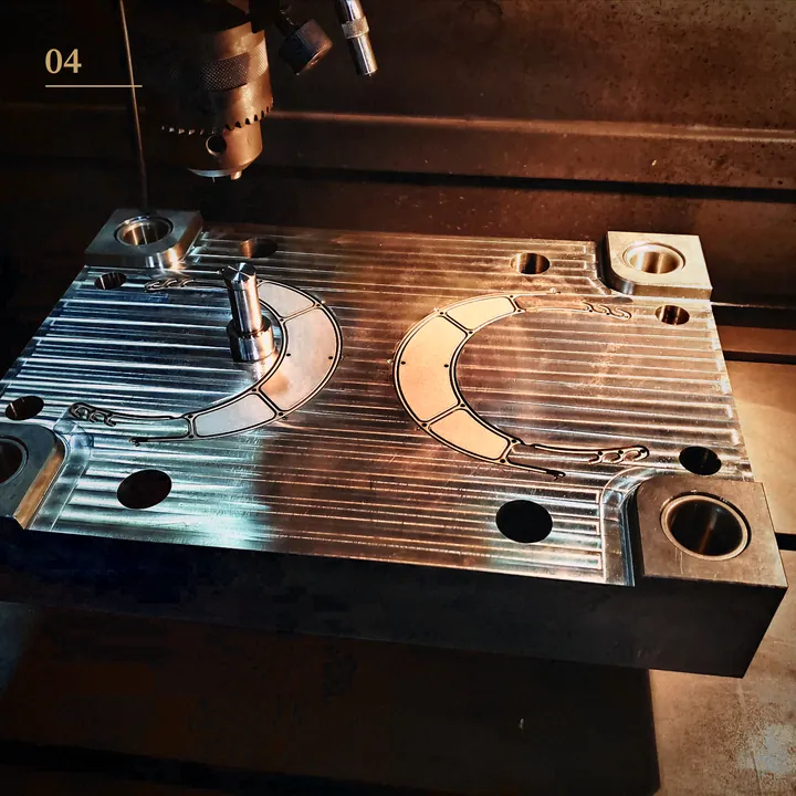
Position behaves differently in a molded part than in a machined one. A hole or boss ends up where the tool steel put it, shifted by shrinkage acting on the distance from the datum. Because shrink is roughly proportional to that distance, a boss far from the datums drifts more than one close to them, and the zone you can realistically hold should scale with datum distance rather than being a single flat number across the part. A moulded-in or heat-set insert adds its own location error on top: the insert pocket behaves as a hole (position at MMC is sensible, with the insert OD playing the mating-pin role), but the metal insert can sit slightly cocked or proud of the nominal, so its functional location is the pocket position plus the insert's own placement tolerance. Core-pin holes are repeatable but a long, slender core pin can deflect under flow, walking the hole off basic in a consistent direction you can often read straight off the deviation signs. None of these are reasons to loosen the drawing blindly; they are reasons to put the datums on the surfaces that actually locate the part and to confirm capability on first articles.
When to use true position vs coordinate tolerances vs profile
| Scheme | Use it when | Watch out for |
|---|---|---|
| True position (this tool) | Locating a feature of size — a hole, pin or boss — in an assembly; when a clearance fit lets you claim MMC bonus | Needs a datum frame; remember the diameter is 2× the radial offset |
| Coordinate ± on X and Y | Quick shop dimensions, non-critical locations | Square zone is smaller than the round one it looks like; a ±0.1 corner is 0.283 diametral; no bonus, no datum logic |
| Profile of a surface | Locating and controlling a surface, edge or non-size feature where position does not apply | Different inspection; ASME reserves position for features of size and uses profile for surfaces |
The square-versus-round point is the practical one. A plus/minus 0.1 box reaches 0.1 along each axis but 0.141 radially at its corners, which is 0.283 as a diameter — so coordinate tolerances accept a corner that a 0.283 position zone would also accept, while giving a smaller usable round area in the middle. Switching a located hole from ± to true position with an MMC modifier usually gains real, defensible tolerance rather than losing it, which is why assemblies that mate round pins to round holes almost always use it.
Datum shift is not bonus
One warning the tool prints deserves spelling out. A material-condition modifier can sit on a datum feature of size as well as on the located feature. When it does — shown as MMB or LMB, the maximum or least material boundary — it does not add bonus to each controlled feature. Instead it allows datum shift: the entire part is free to translate and rotate inside the datum reference frame as the datum feature departs from its boundary. That is a different allowance, applied to the whole pattern at once, and it is not summed feature-by-feature the way bonus is. This calculator models feature bonus only; if your drawing references a datum feature of size at MMB or LMB, let your CMM or inspection software apply the datum shift, and treat this tool's result as the feature-bonus part of the picture, not the whole of it.
ISO 1101 and ASME Y14.5
The position arithmetic is identical under ISO 1101 and ASME Y14.5: the diametral zone and the 2×√(dx²+dy²) relationship do not change across standards. The modifiers do carry different names — ISO uses the maximum and least material requirements (per ISO 2692) where ASME uses MMC and LMC — and the biggest default difference sits one level up: ASME's Rule #1 ties size and form together so that a feature at MMC must also be perfect in form, while ISO follows the independency principle (ISO 8015), where each tolerance is met independently unless an envelope requirement is called out. For a position number alone that distinction does not change the result, but it changes what else the drawing is promising, so read which standard governs before you lean on the calculated allowance. We cite ASME Y14.5 and these references as the governing sources; this page does not reproduce the standard, and for a contractual judgement a current copy of Y14.5 should be the final word.
Common mistakes
- Forgetting the factor of two, or doubling a CMM number that was already diametral. Decide once whether your number is radial or diametral and label it.
- Awarding bonus on an out-of-size feature. If the actual size is outside its limits the part is scrap on size and the bonus is void — the naive math gives a tempting, wrong allowance.
- Applying bonus at RFS. No modifier means no bonus, regardless of size.
- Putting position on a plane or a surface. Position is for features of size; use profile for surfaces.
- Mixing inch and millimetre inputs between the size and the offsets. Keep every field in one unit system.
- Confusing datum MMB/LMB with feature bonus. A datum modifier shifts the frame; it does not add to each feature's tolerance.
Sources for the method. The true position formula and the MMC/LMC bonus rules follow the public descriptions in widely used GD&T training references, including GD&T Basics (true position and maximum material condition) and a Quality Magazine tutorial by a university metrology instructor, all of which give the diametral zone as two times the root-sum-square of the offsets and the bonus as the feature's departure from its material condition. These are cited as secondary to ASME Y14.5, the governing standard, whose text this page does not reproduce; clause-level wording and any contractual interpretation should be confirmed against a current copy of the standard.
Reviewed by the JCH tooling team · updated November 2026
Questions and answers
What is the true position formula?
For a cylindrical zone it is 2×√(dx²+dy²), where dx and dy are the measured X and Y offsets of the feature from its basic location. The factor of two is there because position is stated as a diameter while √(dx²+dy²) is only the radius. For a spherical zone (an S∅ callout or a point in space) add the Z term: 2×√(dx²+dy²+dz²). A normal cylindrical hole is a 2D case — the along-axis direction is not controlled by that position callout.
How do you calculate bonus tolerance at MMC and LMC?
Bonus applies only to a feature of size with an Ⓜ or Ⓛ modifier. Internal feature (hole/slot): bonus at MMC = actual−MMC, at LMC = LMC−actual. External feature (pin/boss): bonus at MMC = MMC−actual, at LMC = actual−LMC. At RFS the bonus is zero. Add the bonus to the stated position tolerance; the feature passes if the deviation is less than or equal to that total. The actual size must be within its size limits or the bonus is void, and the bonus can never exceed the full size tolerance.
Does an MMC modifier on a datum give bonus tolerance?
No. A modifier on a datum feature of size (MMB or LMB) produces datum shift — the whole part may translate and rotate in the datum frame as the datum feature departs from its boundary — not a feature-by-feature bonus. Feature bonus comes only from a modifier inside the located feature's own control frame. The two are different allowances and are not added together. This calculator models feature bonus only; for an MMB/LMB datum, let your CMM software apply the shift.
Why is true position twice the offset distance?
Because the tolerance zone is a cylinder specified by diameter, not radius. The quantity √(dx²+dy²) is how far the axis sits from basic — a radius — so you double it to compare against a diametral tolerance. Equivalently, true position is the diameter of the smallest cylinder centered on the basic location that still contains the feature axis. Many CMMs report the radial deviation, so a reported 0.10 can mean a 0.20 diametral position; always confirm which you have.
What position tolerance is realistic on a plastic boss or molded hole?
There is no single number — it depends on the resin, the tool, how far the feature sits from the datums and how the part is restrained when measured. The useful principle is that molded position is set by the tool steel plus shrinkage on the distance from the datum, so far-from-datum features drift more and the zone you can hold scales with that distance. A warped part can also rock on its datums and read worse than it assembles. Match the datum scheme to how the part mounts and confirm capability on first articles; our tooling team can help set a realistic scheme.
Is true position with no modifier (RFS) different?
Yes. RFS (regardless of feature size) is the default when no modifier is shown and grants no bonus, so the total allowed equals the stated tolerance alone. It is the conservative case, used where the fit is functionally sensitive. The worked examples show why it matters: an offset that passes comfortably with a full MMC bonus can fail at RFS, which is exactly why designers add the MMC modifier wherever a clearance fit justifies handing back tolerance as the hole grows or the pin shrinks.
Ask JCH about position and GD&T
Not sure which modifier to call out, why your CMM position looks double what you expected, or what datum scheme a molded part should use? Ask our AI assistant. It answers from this website, and our tooling team follows up if you want.
AI assistant. Answers can be wrong; nothing it says is a quote or a promise.
Need a datum scheme that passes on the CMM and in the assembly?
This calculator gives an engineering estimate. Our tooling team helps set the datums, the modifiers and the realistic position zones for molded and machined features, so the parts measure well and still fit where they have to fit.
Book a 30-min call Send a drawing or sample