Why are there round marks on my molded part, and can they be moved?
The round marks are ejector pin marks: the outlines of steel pins that push the part off the mold core. They can usually be moved to hidden faces, made larger and shallower, or replaced by blades, sleeves or a stripper plate. The cheap time to decide is before the tool is designed, by marking no-pin zones on the drawing.
Those small round marks, usually on the inside or underside of a part, are ejector pin marks, sometimes called witness marks. They are where steel pins pushed the part off the mold after it cooled. Nearly every molded part has them. The useful questions are where they go, how visible they are allowed to be, and what the alternatives cost.
Why the part needs pushing at all
Plastic shrinks as it cools, and on the core side of the tool it shrinks onto the steel it was formed around. Molds are built so the part stays on the moving half when the mold opens; as explained in cavity and core, that is the half carrying the ejection system. Plates behind the core drive a set of hardened pins forward, and their flat ends push on the part until it drops or a robot takes it. Each pin face is part of the molding surface while the plastic fills, so it leaves an outline. Protolabs' guide to ejector pins puts it simply: pins live in the B-side mold half, need a flat pad to push against, and in some cases leave marks.
What the mark tells you
A pin set exactly flush leaves a faint circle and maybe a slight gloss change. A pin that sits a little long presses a shallow dimple into the part; one that sits short leaves a small raised disc. A pin or bore that has worn leaves a thin ring of flash around the mark. Deep dents, white stress spots or a part that bows between pins mean the part is being pushed too hard or too soon, usually because it is still soft, the draft is too low, or there are too few pins. On a textured face the smooth pin pad shows up even when flush, which Protolabs flags as a common cosmetic surprise.
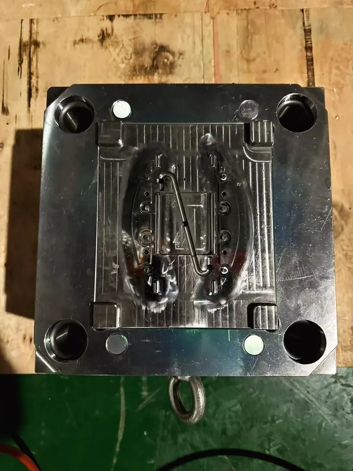
Can they be moved? Yes, within limits
The toolmaker can place pins almost anywhere on the core side that is flat enough to push on, strong enough to take the load, and away from cooling lines and other steel. You get the most freedom if you say what matters before the tool is designed. Protolabs proposes pin and gate locations for customer sign-off before an order is finalized, and most toolmakers will do the same if asked. After the tool is built, moving a pin means plugging the old hole, which leaves its own visible outline, and drilling a new one.
Celanese's Vectra design guide gives the toolmaker's view: put ejectors at weld lines and where shrinkage grips (corners), push the part off evenly, and err on the side of too many pins rather than too few. It also warns that if a satisfactory ejection system cannot be designed on paper first, it will be difficult to add to the finished mold. That is the real constraint on "can they be moved": cosmetic wishes have to leave room for enough push.
| Method | What it pushes on | Mark it leaves | Typical use |
|---|---|---|---|
| Round pin | A flat pad on a wall, rib end or boss | Small circle | The default for most parts |
| Blade (flat) ejector | The end of a thin rib | Thin rectangle on the rib tip | Slender ribs and projections that a round pin cannot fit |
| Sleeve | The full ring at the end of a boss, around a core pin | Ring on the boss end | Screw bosses and tubes that grip their core pin |
| Stripper plate or ring | The whole edge of the part | No round marks; a line on the edge | Cups, lids, thin round parts, cosmetic interiors |
| Air poppet | A small valve area under the part | Small outline at the valve | Deep flexible parts; used alongside other ejection |
The DME catalog of standard pins, sleeves and blades shows the practical range: inch-series ejector pins from 1/32 in up to 1 in diameter, sleeves sized around matching pins, and blades as thin as 0.024 in. Avient's TPE molding guide adds that blades, sleeves and stripper rings are all usable for ejection and that air ejection helps strip deep or undercut soft parts.
Worked example: why bigger pins mark less
Suppose a hypothetical PC/ABS lid needs a fixed ejection force to break it free; call it F. If the tool has four 3 mm pins, each face has an area of pi x 1.5 squared = 7.07 mm2, so the four together push on 28.3 mm2. Swap them for four 6 mm pins and each face is 28.3 mm2, so the total is 113 mm2. The force is the same, but the pressure on the plastic under each pin drops to a quarter. Avient's guide says pin diameter should be as large as possible to minimize push-through marks, and that larger pins allow easier ejection of warmer parts. Adding two more 6 mm pins drops the face pressure by another third.
The force itself depends mostly on draft, texture and how hard the part grips the core. Protolabs' draft guidance is a minimum of 0.5 degree on vertical faces, 1 to 2 degrees as a good working range, at least 3 degrees under a light texture and 5 or more under a heavy one. Halving the grip with better draft does as much for the marks as doubling the pin area. The draft angle calculator and draft angle answer cover that side.
How to put pin rules on a drawing
- Shade or note the cosmetic faces and write "no ejector marks" on them.
- On faces where marks are acceptable, give a limit, for example flush to 0.1 mm proud, no depressions, no flash ring. Use your own numbers; they belong in the quality agreement.
- If a face must stay clean but has no other place to push, add sacrificial pads or small bosses on a hidden face; Protolabs suggests adding bosses as ejector pads when rib edges are too small.
- Ask for the pin layout drawing with the tool design and approve it like a dimension.
- On textured parts, say whether the pin faces may be left smooth or must carry the texture.
Failure modes worth knowing
- Pins in thin walls can push through or leave a dent visible on the show side. Protolabs notes a pin set back to make a recessed pad leaves a thicker local section, which can sink on the back face; one set too far the other way can leave a hole.
- Too few pins bend the part while it is soft. That looks like warp, and it is easy to blame the resin; see why parts warp.
- Worn pins grow flash rings over time. That is maintenance, not design, and belongs in the tool upkeep plan in protecting your tooling.
- Sticking on the wrong half. If the part stays on the cavity side, the pins never touch it. Celanese notes slight undercuts or roughened faces can be used to keep the part on the ejector half.
When the answer changes
If both faces of a part are cosmetic, the honest options are a stripper plate, ejection on a hidden edge or flange, a trimmed tab, or accepting a small mark at an agreed place. Very soft materials such as TPE need more and larger pins or air. Very stiff, fast-cycling grades can be pushed hot only if the pins are designed not to dent the part, as the Vectra guide notes for LCP. For a clear part, any mark shows from both sides, so ejection usually moves to the edge. If the marks on your first samples surprise you, raise it at first-article review, before the tool is approved.
Common questions
Are ejector pin marks a defect?
Not by themselves. Almost every molded part has them, and a flush, clean mark on a hidden face is normal. They become a defect when they land on a cosmetic surface, sit outside the agreed height or depth, carry a flash ring, or show stress whitening, which points to the part being pushed too hard.
Can ejector pins go on the outside of a part?
Usually not, because the outside is normally formed by the cavity half, which has no ejection. A tool can be arranged so the outer face is on the core side, but then the cosmetic face moves. The common answer is to keep pins on the inside, on flanges, or on bosses and ribs that nobody sees.
Can the pin mark be textured to match the surface?
Often it can. Pin faces can be textured along with the core, though they are small, rotate in some designs and wear, so the match is rarely perfect. On contoured surfaces a pin end can be machined to the shape, but it must then be keyed so it cannot turn. Agree the expectation before texturing.
How many ejector pins does a part need?
Enough to push the part off evenly without denting or bending it. That depends on part size, draft, texture, how stiff the resin is when hot, and how hard the part grips the core. Resin makers' guides lean toward more and larger pins; a toolmaker sets the count during mold design.
What does it cost to move a pin after the tool is built?
It is a tool change: the old hole is plugged with a matching insert, which can leave a faint outline of its own, and a new hole is drilled and fitted, if the steel and cooling lines allow it. It is simple on some tools and impossible on others, which is why pin layout is best approved on the design.
Sources
- Protolabs - Using ejector pins properly on molded parts
- Protolabs - Draft angle guidelines for injection molding
- Celanese - Vectra LCP Design Guide (ejection, draft)
- Avient - GLS TPE injection molding guide (part ejection)
- DME - Imperial pins, sleeves and blades catalog
Send the part file and the quantity you expect to run, and we'll review it before you commit to tooling. NDA first if you want one.
Send a part for reviewBook a 30-minute call