What causes flash on injection molded parts, and how is it fixed?
Flash is a thin fin that forms when melt escapes through a gap in the closed mold. The gap comes from a worn or damaged shutoff, a vent cut too deep, plates bending under pressure, or a clamp that can't hold the shot. Runny resins like nylon leak first. Where the fin sits says whether to fix steel or settings.
Flash is a thin skin of plastic that forms outside the part outline, in a gap that should have been sealed shut. It most often runs along the parting line, but it also shows up at vents, around ejector pins, at slide and insert faces, and anywhere two pieces of steel meet around the cavity. A fin is more than a trimming chore. It tells you the mold opened, bent or wore somewhere, and that cause tends to grow if nobody deals with it. Fictiv says it plainly: flash that is heavy on a new tool will probably get worse as the tool wears.
Flash, a witness line or mismatch?
Three marks at the split get lumped together, and only one of them is flash.
- Witness line: the hairline where the two halves meet. Every split leaves one. There is nothing to catch with a fingernail, and no process setting removes it; its position is chosen when the tool is designed.
- Mismatch: a step where one half sits slightly off the other. The faces don't line up, but no extra material sticks out. That is an alignment problem (guide pins, interlocks, heat), not a sealing one.
- Flash: a fin that projects past the part edge or into a hole. Fictiv puts the general industry limit at under 0.004 in (0.10 mm) and says 0.002 in (0.05 mm) or less is possible with extra care in tool design, build and fitting.
Location decides how much a fin matters. On a sealing groove, a mating edge or inside a screw hole it is a function problem. On a hidden inside edge it may be harmless. Say which edges are which on the drawing, because the molder cannot guess.
The force balance behind every fin
Once the cavity is full, the melt pushes the halves apart with a force equal to the average cavity pressure times the projected area: the part's shadow seen along the opening direction, plus any cold runner. The clamp has to beat that force, and the steel has to stay flat while it does. Flash appears when either side of the balance fails, across the whole tool or in one small spot.
Sizing rules for the clamp vary a lot. Jeremy Williams, writing in Plastics Technology, says tonnage factors range from 2 to 10 tons per square inch of projected area and suggests 3 as a starting point. The clamp tonnage calculator on this site uses resin ranges instead, 4 to 5 for unfilled nylon. Jim Fattori's Plastics Technology column adds two corrections. Dividing peak injection pressure by area overstates the need, because pressure drops through the nozzle, sprue, runner and gate, and he puts the plastic pressure needed at the end of fill to pack a part at about 3,000 psi. But the nameplate also overstates what is available: he cites the common figure that 10% or more of the clamp can go into aligning the halves, and on molds with a high spot he saw 30 to 50%.
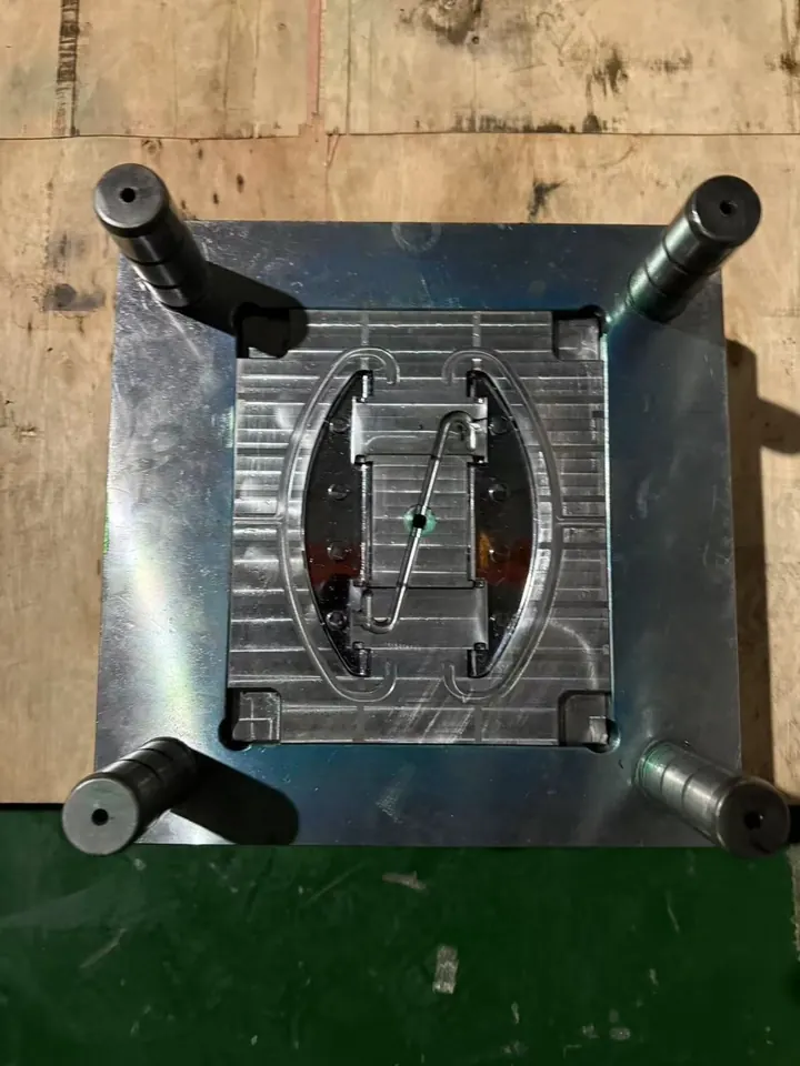
Causes in the tool
Shutoffs that no longer seal
Randy Kerkstra's rule in Plastics Technology is that every shutoff and parting line has to be "true net": closed tight, with no gap, damage or debris holding the mold open. It fails in ordinary ways. A part left in the mold gets closed on and dents the land. A crumb of plastic or a burr sits on the face. Repeated polishing rounds over the sharp cavity edge. A sliding shutoff with too little draft scuffs every cycle until it no longer meets its partner. Lands also simply wear, which is why old tools flash. This kind of fin sits in the same place every shot, and usually in one cavity.
Vents ground too deep
A vent is a deliberate gap, so it is the easiest place for melt to escape. The safe depth depends on the resin. DuPont's Zytel molding guide gives 0.012 to 0.020 mm for its nylons, with a vent land of 0.8 to 1.0 mm at most, and says low-viscosity grades should start shallow and be opened only as needed. Celanese caps Vectra LCP vents at 0.025 mm and wants them polished. A vent cut for a stiffer resin, or opened on the press to cure a burn, can be several times too deep for nylon. Fins found only at the vents point here. How mold vents work covers placement, and the vent depth guide lists ranges by resin.
Plates and slides that bend
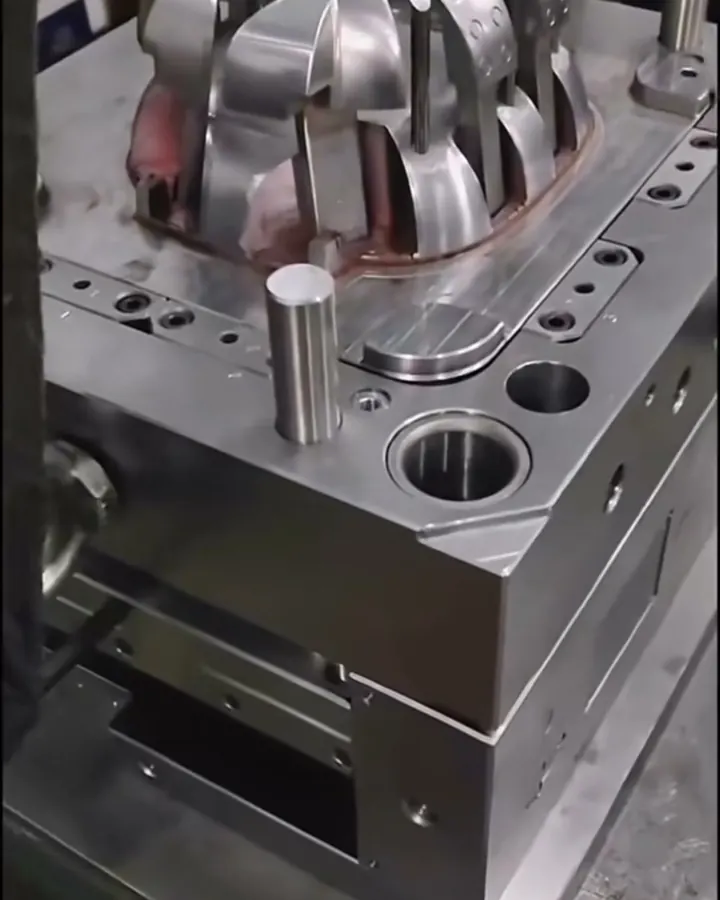
The core plate spans the open space where the ejector plates travel. Under cavity pressure it bows in the middle unless support pillars hold it from the clamp plate. DuPont notes that thin-wall parts in its resins can need specific injection pressure above 100 MPa (14.5 kpsi), and lists stiff mold construction as a contribution to flash-free molding. Kerkstra suggests pillar preload of around 0.003 to 0.005 in, and has seen tools that needed up to 0.015 in in the center. Deflection also happens sideways. He describes a slide tool whose side moved 0.012 in under pressure, and asks for hydraulic core cylinders sized for at least 1.5 times the peak plastic pressure. Flash from bending tends to start near the runner and gate, where pressure is highest, and grows as injection pressure rises. Fictiv suggests having the molder read the dial indicators at the platen and add support if the tool moves.
Halves that don't meet square, and worn pins
Fattori's numbers show how little it takes. Tie bars should stretch within 0.002 in of each other, or the mold is loaded unevenly. In his experience, 0.002 to 0.003 in of misfit in the wrong spot took a significant amount of clamp just to seal the cavity edge. Heat moves steel too: his thermal example, 24 in x 40 °F x 0.0000063 in/in/°F, works out to about 0.006 in of misalignment. Ejector pins and their bores wear as well, leaving a ring of flash around each pin mark; that one belongs to maintenance, as the ejector pin marks page explains.
Causes in the process
A shot has stages, and Fictiv's first request is fill-only parts: stop the shot at the end of injection, before pack and hold, and see whether the fin is already there. That one test splits the process causes in two.
- Flash during fill: injection rate too fast, melt too hot, or more pressure than the flow length needs. Celanese's remedies for flashing Vectra start with lower injection pressure and rate, and a cooler melt from slower screw speed or lower barrel heat. Fictiv adds long residence time, which thins the melt the same way heat does.
- Flash during pack and hold: pack pressure set higher than the part needs, switchover from fill to pack happening late, or a shot so big there is no cushion left. Celanese asks for a 3 to 5 mm melt cushion and a smaller shot when Vectra flashes, and says the check ring has to work, because a leaking ring makes every shot different.
- Clamp setting: the press may be big enough on paper but set low, or simply too small for the projected area. Moving the mold to a larger press is the last item on Celanese's flashing list. Turning clamp up as a cure has a cost: Williams lists crushed vents, a rolled parting line, broken inserts and cracked core or cavity blocks from over-clamping.
Causes in the material
A thin, runny melt finds gaps a stiff melt would bridge. Nylon is the usual example. LCP is runnier still, but it freezes so fast that Celanese says Vectra won't flash if vents are kept to 0.025 mm or less. Celanese describes Vectra's melt viscosity as extremely low and says it falls further as injection rate goes up, which is why Vectra vents are kept small. Nylon adds moisture to the story. DuPont's guide says wet nylon has lower melt viscosity and can over-pack parts and runners, and that above 0.25% moisture the parts lose properties and flash easily. So a nylon job that starts flashing out of nowhere needs a moisture reading before anyone touches the clamp; see drying hygroscopic resins. A grade change can do the same thing. Williams lists melt flow rate among the factors that set tonnage, comparable only within one resin type; a higher-flow grade of the same resin needs less tonnage to fill, and in our reading it also finds gaps more easily.
Reading the fin before changing anything
| Where and when it shows | Most likely source | First check |
|---|---|---|
| One spot, one cavity, from the first trial | Shutoff fit or a vent at that spot | Spot the halves with ink; measure the vent |
| At every vent | Vents too deep for this resin | Measure depth against the resin guide |
| Around the whole split, all cavities, only after pack | Pack too high or clamp short | Fill-only parts; tonnage math |
| Near the gate, or mid-span on a big flat part | Plate or slide deflection | Dial indicator under pressure; pillar support |
| Rings around pin marks | Worn pins or bores | Pin clearance, tool upkeep record |
| Crept in over a long run | Land wear | Refit or insert the worn shutoffs |
| Sudden, after good production | Something changed | Moisture, resin lot, debris on the face, press, setup sheet |
On a multi-cavity tool, look at every cavity before deciding. A fin in one cavity and not its twin is almost never the clamp, which loads them all.
Worked example: one cavity flashing on a nylon cover
A hypothetical unfilled PA66 cover measures 120 x 90 mm with a 2.0 mm wall. It runs in a two-cavity tool with a balanced cold runner that adds about 10% to the projected area, on a 150-ton press. Cavity 2 shows a fin about 0.15 mm high on the edge farthest from the gate. Cavity 1 is clean.
Is the clamp big enough? One cavity is 120 x 90 = 10,800 mm2, or 10,800 / 645.16 = 16.74 in2. Two cavities plus runner: 16.74 x 2 x 1.10 = 36.83 in2. At Williams' 3 tons/in2 starting factor the job needs 110 tons. At the 4 to 5 tons/in2 nylon range it needs 147 to 184 tons. Take Fattori's 10% for alignment off the 150-ton nameplate and about 135 tons remain, enough to hold an average of 135 x 2,000 / 36.83 = 7,331 psi across the shot. If packing needs about 3,000 psi, the load is 36.83 x 3,000 / 2,000 = 55 tons. By the nylon rule of thumb the press is short (about 135 t usable against 147 to 184 t), but it has room for a sensible pack.
What the fin says. A short clamp would open both cavities, not one edge of one. The fin is already there on a fill-only shot, smaller, so pack pressure is not the whole story. Measuring the land at that edge finds a vent ground 0.04 mm deep, twice DuPont's 0.020 mm upper limit for Zytel.
The fix. Cutting pack until the fin disappears would leave a short or sinking part, and raising clamp does nothing to a gap machined into steel. The repair is in the tool: weld and recut that vent to 0.012 to 0.020 mm with a land of 0.8 to 1.0 mm, then re-sample. Had the fin run around both cavities and grown only during pack, the process would come first, then a bigger press. The tonnage calculator, at its 4.5 tons/in2 nylon midpoint plus a 10% margin, asks for 182 tons and rounds up to a 200-ton machine.
Fix it in this order
- Find what changed. Clean the parting line, look for debris, dents and a stuck part, and compare today's setup with the approved one.
- Check the material. Moisture reading for nylon and other hygroscopic resins; confirm grade and lot.
- Locate the stage. Fill-only parts. Then set pack and hold to what the part needs, move switchover earlier, and keep a real cushion.
- Bring the melt back into its window. Melt temperature, residence time and injection speed against the resin datasheet.
- Check the clamp. Work out the tonnage from projected area. Set it, or move to a bigger press if it is short. Don't run at maximum as a habit.
- Repair the tool. Spot and refit shutoffs, recut over-deep vents, add or preload pillars, stiffen slides, replace worn pins. Do it once, then re-sample.
Tool or process: how to decide
Fix the steel when the fin sits in the same place from the first trial, when a vent or shutoff measures wrong, when the tool moves under pressure, or when the only settings that stop the fin also bring on short shots or sink. Kerkstra's view is that a change to the tool gives the more robust answer. A process window squeezed to hide a leak is fragile; the next resin lot or a warmer day can bring the fin back. Fix the process when the fin appeared after a change, shows on every cavity, and disappears on a fill-only shot. Some flash is a design question. Kerkstra describes a large glass-filled part that needed more than 12,000 psi to fill when gated at one end and about 5,500 psi gated in the middle, the difference between a 300-ton and a 120-ton press. Gate type and position are set before steel is cut. Trimming is containment, not a cure: Fictiv notes hand trimming adds labor and part-to-part variation.
When the answer changes
- Old tool, new flash. Gradual flash on a tool with a long run behind it is wear. Budget refitting as upkeep; protecting your tooling covers the routine.
- Soft tooling. Aluminum lands dent and wear sooner than hardened steel, so plan on more refits for a long run; see aluminum vs steel tooling.
- Family molds. Different parts in one tool fill at different rates, so a small part can over-pack and flash while a large one is still filling. Family molds explains the trade.
- Sealing and mating edges. Ask for the tighter flash figure on those edges only, and approve it on parts at first-article review.
For how flash sits among the other common defects, see the tool-or-process defects note. The defect troubleshooter ranks likely causes when the symptom is less clear-cut.
Common questions
How much flash is acceptable on a molded part?
Fictiv gives under 0.10 mm (0.004 in) as the general industry standard, and says 0.05 mm (0.002 in) or less can be held with more care in tool design, build and fitting. The right limit depends on the edge: none on sealing faces, mating edges and holes, more on hidden edges. Put the limit on the drawing and approve it on first articles.
Will moving the mold to a bigger press stop flash?
Only if the clamp was really short. If the fin sits in one spot, at the vents or around pins, more tonnage will not close a gap machined into steel, and over-clamping can crush vents and roll the parting line. Work out the required tonnage from projected area first and compare it with what the press can actually apply.
Why does nylon flash more easily than ABS or polycarbonate?
Molten nylon is thin at fill and runs into gaps that a stiffer melt bridges, so its vents must be shallower; DuPont lists 0.012 to 0.020 mm for Zytel. Moisture makes it worse, because wet nylon flows even more easily. A tool vented for a stiffer resin often flashes when it is switched to nylon.
Does flash mean the mold is worn out?
Usually not. On an older tool, parting-line flash generally means lands or shutoffs have worn and need refitting, which is routine upkeep. On a new tool it points to fit, venting, plate support or the process. In both cases the job is to find the leak and repair that spot, not to replace the mold.
Can flash just be trimmed off instead of fixed?
As a stop-gap, yes. Fictiv warns that hand trimming adds labor and part-to-part variation, and a trimmed edge rarely looks like a molded one. It also hides the cause, which usually gets worse as the tool runs. Treat trimming as containment while the leak is found and fixed, not as the process of record.
Sources
- Plastics Technology - Flash-Free Molding: Part 1 (Randy Kerkstra)
- Plastics Technology - Clamp Pressure and Cavity Land Area (Jim Fattori)
- Plastics Technology - Clamp Tonnage: More Is Better... Right? (Jeremy Williams)
- Fictiv - Injection molding flash: causes and fixes (Cameron Moore, Steve Melito)
- DuPont - Zytel and Minlon nylon resins molding guide
- Celanese - Vectra LCP design guide (venting, flashing remedies)
Send the part file and the quantity you expect to run, and we'll review it before you commit to tooling. NDA first if you want one.
Send a part for reviewBook a 30-minute call