How long does mold design take?
There's no single honest number — it's set by the part, not the calendar. A simple single-cavity part with clean data moves through design quickly; undercuts, multiple cavities, tight tolerances, or incomplete data take longer. What's worth knowing is the phases and the drivers, so you can see where your part falls — and that the biggest delays come from changes and missing data, not the design work itself.
JCH coordinates DFM, mold design, and the tool build through a manufacturing network; this page is general guidance, not a quote.
The phases (design, then build)
- DFM review — design-for-manufacturability: checking the part molds well (walls, draft, gates, problem features) before any mold is drawn.
- Mold design — laying out cavity and core, cooling, ejection, gating, and any actions (lifters/slides) for undercuts.
- Design review & sign-off — you approve the design before steel is cut.
- Tool build — a separate, usually longer phase: cutting and finishing the steel to the approved design.
Mold design is the front end; the tool build is normally the long pole — design is typically a fraction of the build. When people ask "how long for the mold," they usually mean design plus build, and the build dominates the total.
What drives the timeline
| Driver | Faster ←→ slower |
|---|---|
| Part complexity | Simple box ←→ undercuts, lifters/side-actions, living hinges |
| Cavitation | Single cavity ←→ multi-cavity or family tool |
| Data readiness | Clean STEP + drawing ←→ STL-only or missing tolerances |
| Surface & tolerance | Rough internal part ←→ cosmetic, tight-tolerance part |
| Review cycles | Quick sign-off ←→ slow back-and-forth |
These compound: a multi-cavity tool with tight tolerances and a cosmetic finish takes longer than any one of those drivers alone.
What you control
- Send clean data up front — a solid model (STEP or native) plus a dimensioned drawing, so no time is lost rebuilding geometry or guessing tolerances (see CAD file formats).
- Lock the design first — changes made mid-design ripple into cooling, ejection, and gating and effectively restart work.
- Respond fast — to DFM questions and the design review; review cycles are often the real bottleneck.
- Name the critical dimensions — so design effort concentrates where it matters.
Why DFM first saves time
Catching a molding problem on screen is quick; catching it in steel is not. DFM flags a thin wall, a missing draft angle, or a bad gate location while it's still an edit to a CAD file. Skip it, and the same problem surfaces after the tool is cut — where the fix is steel rework and a real schedule hit. The projects that run long are often the ones that rushed past DFM: it feels like an extra step up front, and it's the step that prevents the expensive delay later.
What we need to estimate it
The part (a STEP file and a dimensioned drawing), your target cavity count, the finish and tolerance requirements, and how firm the design is. With those, the design and build can be estimated against your specifics rather than a generic number — and we'll tell you honestly which driver is setting your schedule.
What to check before you sign the mold design
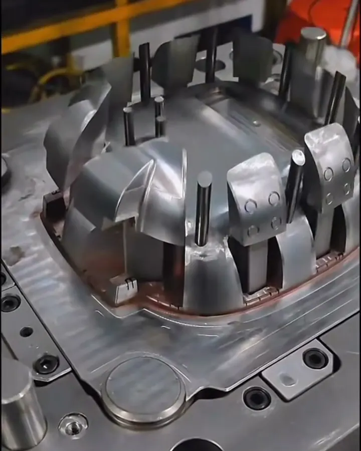
A one-line "looks fine" at sign-off lets open questions through to the steel; checking each item below in writing settles them while they are still drawing edits. Bruce Catoen's part checklist in MoldMaking Technology asks for parting lines, gate position, venting, shrinkage and acceptable sink or warp to be defined before detailed mold design begins.
| Item in the design package | What to look for | If it is missed |
|---|---|---|
| Parting line and split lines | Where the line crosses your part, especially on show faces | A visible line or flash edge on a cosmetic surface |
| Gate type and location | Where the vestige lands and whether that face matters | Gate blush or a trimmed nub where users will see it |
| Ejector pin layout | Pins kept off cosmetic and sealing faces | Witness marks in the wrong place |
| Slides and lifters | Every undercut has a slide or lifter, with room to travel | A missed undercut means the part cannot eject |
| Cooling layout | Lines near thick sections, on both halves | Warp or sink the press settings cannot correct |
| Shrink factor | The value applied and the resin grade it assumes | Every dimension shifts if the grade changes later |
| Steel for each plate and insert | Grade matched to real volume (see the mold steel selector) | Early wear, or an overbuilt tool |
| Flow study, if one was run | Fill pattern, weld line positions, predicted sink areas | A weld line or sink on a feature that needs strength or gloss |
Approve with a marked-up copy and a list of open items. Anything left "to be confirmed" becomes the toolmaker's decision, and reversing it later is a change.
Which changes cost the most schedule, and when
The same edit grows with how far the work has moved:
- Before mold design starts: a CAD edit that the DFM review re-checks.
- During mold design: moving a wall, rib or hole can force the cooling, ejection and gating around it to be redrawn and reviewed again.
- After steel is ordered: a change to the part envelope can make the ordered blocks or mold base the wrong size.
- After machining: adding plastic means cutting more steel, but removing plastic means building steel back by welding or a new insert, which is slower and can mark polished faces.
Two habits help. Send edits as one batch, because each single change restarts the review. And ask for the schedule as named phases with your review steps marked, so you can see which waits are yours.
Sources for this section:
Common questions
How long does mold design take?
No single number — it's set by part complexity, cavity count, data cleanliness, and review speed. Think in phases: DFM review, mold design, your sign-off, then the tool build (a separate, longer phase). Design is the front end; the build is the long pole. A locked, well-documented design is the fast path.
What makes mold design take longer?
Part complexity (undercuts/lifters, thin walls, living hinges), cavitation (multi-cavity/family tools), data gaps (STL-only, missing tolerances), cosmetic/tight-tolerance demands, and slow review cycles. Most slow projects are slowed by missing data or mid-stream changes, not the drafting.
What's the difference between mold design and mold build?
Design is the engineering (cavity/core, cooling, ejection, gating, undercut actions) plus review and sign-off; build is cutting and finishing the steel to that design. They're sequential — sign-off before the build — and the build is normally the longer phase.
What can I do to speed up mold design?
Send a clean solid model + dimensioned drawing up front, lock the design before mold design starts (mid-design changes restart work), respond fast to DFM and the review, and name the critical dimensions. A firm, well-documented part is the biggest schedule lever you control.
Why does DFM come first?
Catching a molding problem on screen is quick; catching it in steel is rework. DFM checks wall uniformity, draft, gates, and problem features before the mold is designed and flags fixes while they're still a CAD edit. Skipping it is a common reason projects run long.
JCH Design & Manufacturing can estimate design and build time for your specific part. Send the STEP file, a drawing, and your cavity-count target.
Book a 30-minute callAsk JCH what sets the mold design schedule
Wondering which features of your part add design time, or what you can prepare to speed things up? Ask our AI assistant. It answers from this website, and our tooling team follows up if you want.
AI assistant. Answers can be wrong; nothing it says is a quote or a promise.