How should screw bosses be designed in molded plastic?
Size the boss from the screw: for thread-forming screws, a hole of about 0.8 times the screw diameter, an outside diameter about twice the screw and about twice the screw diameter of engagement. Then check the base against the wall for sink, core the hole to the floor, add gussets, and set torque from tests.
Every boss is a compromise between the screw and the mold. The screw wants plenty of plastic around it: forming the thread loads the boss in hoop stress, and a pull on the screw tries to shear the formed threads off. The mold wants the boss wall thin, because a thick base cools last and pulls in the cosmetic face on the other side. On a thin-walled housing the screw maker's ratios and the sink rule rarely agree, so most of the work is deciding which one gives, and by how much.
Start from the screw, not the boss
For plastics, the usual fastener is a thread-forming screw with a wide, sharp thread that displaces plastic instead of cutting it. Screw makers publish their boss recommendations as ratios to the screw's nominal diameter d; put those ratios into the CAD first and adjust from there. What changes the answer is the resin. DuPont sorts it by flexural modulus: below about 1,380 MPa a thread-forming screw is fine; between 1,380 and 2,760 MPa thread-cutting screws are generally safer, though nylon and acetal still take thread-forming screws well; and above 6,900 MPa, heavily glass-filled grades can crumble between threads and pull out early. BASF draws the line differently, keeping thread-cutting screws for brittle plastics, thermosets and resins filled above about 50%. Treat that disagreement as a cue to test, not to pick a side.
Where the published rules agree and where they don't
| Dimension | EJOT (screw maker, DELTA PT) | BASF design guide | DuPont design guide |
|---|---|---|---|
| Pilot hole | 0.8 × d; up to 0.88 × d for highly filled or stronger resins | sized for 50–70% thread engagement | hole diameter equal to the screw's pitch diameter (for the highest strip-to-drive ratio); otherwise per screw maker's table |
| Boss outside diameter | 2 × d | ideally 2.5 × d; 2.0 × d or less with ribs if sink is a concern | 2 to 2.5 × the hole diameter |
| Engagement depth | 2 × d | 2.5 × d | 2 to 3 × d in the screw tables it reprints |
| Draft in the hole | as small as possible, 0.5° per side maximum | ¼° to ½° per side | normal molding draft, hole sized at mid-length |
| Entry | counterbore about 1.05 × d, 0.3–0.4 × d deep | counterbore or chamfer about 0.5 mm (0.020 in) deep | — |
All three are starting points. The screw you actually buy has its own table, and that table wins. The screw boss design calculator runs these factors for common resins and checks the sink at the base.
A worked example: 4 mm screw in glass-filled nylon
Take a housing in 30% glass-filled nylon 6 with a 2.5 mm nominal wall, fastened with a 4.0 mm thread-forming screw for plastics.
- Hole. The resin is filled and strong, so use EJOT's upper factor: 0.88 × 4.0 = 3.5 mm. In an unfilled grade the same screw would start at 0.8 × 4.0 = 3.2 mm. DuPont's modulus groups put glass-reinforced nylons among the resins it would rather fasten with thread-cutting screws, so this is exactly the case the torque test below has to settle.
- Engagement. 2 × 4.0 = 8.0 mm per EJOT, 10 mm per BASF. Use 8 mm and confirm with tests; if the clamped lid is 3 mm thick, the screw is 11 mm long and the hole goes deeper than the tip.
- Outside diameter. EJOT gives 2 × 4.0 = 8.0 mm. The boss wall is then (8.0 − 3.5) ÷ 2 = 2.25 mm, which is 90% of the 2.5 mm wall.
- Sink check. BASF warns that a boss base thicker than about 50% of the wall can show sink. At 90% this boss will mark the outside face, so you choose: accept it on a hidden face, texture the face, or follow BASF's alternative of a smaller boss, 2.0 × d or less, held up by ribs.
- Gussets. Tie the boss to the nearest wall or give it three or four gussets. BASF limits gusset thickness at the base to 50% of the wall they stand on, here about 1.25 mm.
- Entry. Counterbore 1.05 × 4.0 = 4.2 mm across and about 1.2–1.6 mm deep. EJOT says this relieves edge stress and stops the top of the boss from splitting as the first thread forms.
The numbers show the real decision: on a 2.5 mm wall, a screw-maker boss and a sink-free face can't both be had without ribs or coring. That is the decision to make in CAD, not at the first shots.
Coring, sink and the hole floor
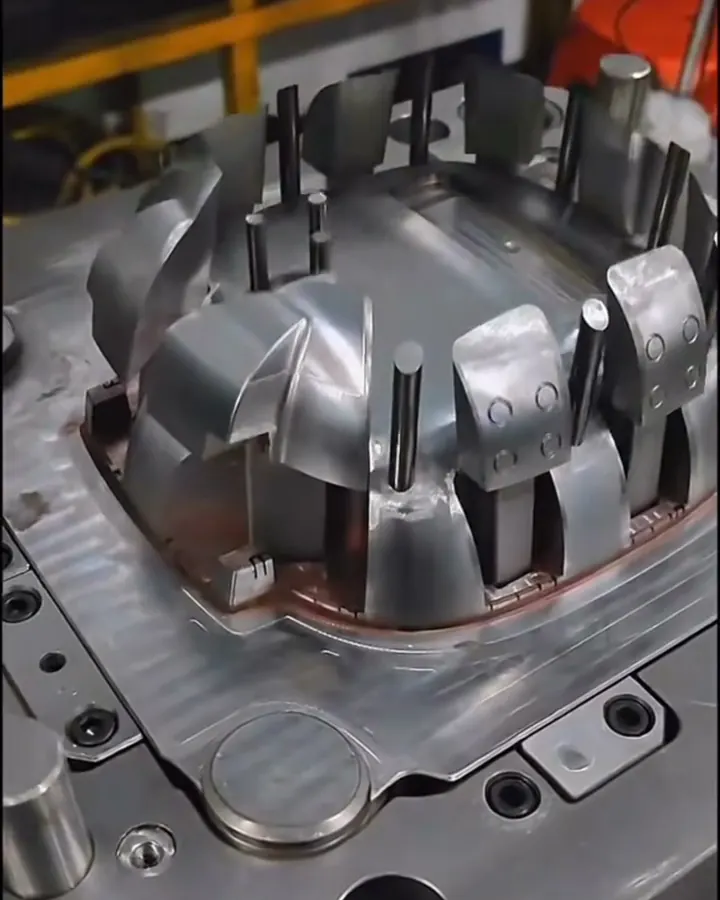
Carry the core pin down to the floor of the part. A hole that ends halfway up leaves solid plastic under it, right where the boss meets the floor, and that mass shows up as sink on the outside face and voids inside; see what causes sink marks and how wall thickness drives them. If the hole must be blind, DuPont suggests the bottom be no thinner than about one sixth of the hole diameter to avoid bulging. Note also DuPont's general caution that a blind core pin held at one end can be pushed off center by the flow; tall bosses with slender pins need the pin stiffened or stepped. BASF advises against free-standing bosses for the same reason it calls for gussets, and Protolabs notes that tall bosses may need vents and up to 3° or more of draft on the outside to eject cleanly.
Torque: the number assembly actually sets
A thread-forming screw has three torques worth knowing: the drive torque to form the thread, the strip torque at which the plastic thread shears, and the seating torque the driver is set to. BASF's guidelines are a strip-to-drive ratio of at least 3:1, with the gap between the two mattering more than the ratio, and a seating torque no more than two thirds of strip. EJOT asks for a wide gap between installation and stripping torque and a driver with torque or angle shut-off.
Suppose sample bosses from the example measure 0.9 N·m to drive and 3.0 N·m to strip. The ratio is 3.3:1, which passes. Two thirds of strip is 2.0 N·m, so set the driver below that, leaving room for weld lines and resin lot changes. If the ratio comes in near 2:1, shrink the hole slightly or lengthen the engagement before blaming the screw. EJOT's own list of what shifts these numbers on real parts includes processing conditions, distance from the gate, weld lines and filler texture, which is why the test has to be on molded bosses, not drilled bar stock.
Failure modes to design out
- Split boss. Hoop stress from too small a hole or too thin a wall, often starting at a weld line where flow met around the core pin. No counterbore makes it worse.
- Stripped thread. Driver set too close to strip torque, or a hole opened up by too much draft at the entry.
- Loosening over time. Plastic under the screw head relaxes. BASF advises larger heads or washers to spread the load, and warns against flat-head screws, whose cone wedges the boss apart.
- Worn-out thread. BASF puts thread-forming screws at about 3 to 7 reinstallations. For more service cycles, use a metal insert.
When to stop using a plain boss
Switch to an insert when the joint is serviced often, carries a steady clamp load, or sits in a resin that won't hold a formed thread; the options are compared in this note on threaded inserts and in whether to mold threads or add them later. For light covers that never come off, a snap fit or a heat stake may remove the boss entirely; see ways to join two molded parts.
Common questions
What size hole does a thread-forming screw need in plastic?
EJOT's starting point for its screws is 0.8 times the screw's nominal diameter, rising to 0.88 times for highly filled or stronger resins. BASF instead sizes the hole for 50 to 70 percent thread engagement. Always finish with the table for the exact screw and a drive test on molded parts.
How thick should the wall of a screw boss be?
The screw wants a boss about twice its diameter, which often makes the boss wall nearly as thick as the main wall. BASF warns that a boss base above about half the wall thickness can sink. Accept the sink on a hidden face, texture the face, or use a smaller boss supported by ribs.
Why do screw bosses crack?
Usually from hoop stress. A hole that is too small, a boss wall that is too thin, a weld line running down the boss, a missing counterbore at the entry, or a flat-head screw wedging the top apart can each start a crack. Glass-filled and brittle grades are the least forgiving of these.
How tight should screws be driven into plastic bosses?
Measure drive and strip torque on molded samples first. BASF suggests a strip-to-drive ratio of at least 3 to 1 and a seating torque of no more than two thirds of the strip torque. Use a driver with torque or angle shut-off so the setting holds on the line.
How many times can a thread-forming screw be reinstalled?
BASF puts it at roughly three to seven times before the formed thread wears out, depending on the resin and screw. If the product will be opened for service more often than that, specify a brass or steel threaded insert in the boss instead of relying on the plastic thread.
Sources
- EJOT - DELTA PT screw for thermoplastics: design recommendations (brochure)
- BASF - Design Solutions Guide (bosses; self-tapping screws) (copy hosted by hankyan.com)
- DuPont - General Design Principles for DuPont Engineering Polymers, Module I (bosses; self-tapping screws) (copy hosted by Distrupol)
- Protolabs - 5 Ways to Master Complex Features in Injection-Molded Parts
Send the part file and the quantity you expect to run, and we'll review it before you commit to tooling. NDA first if you want one.
Send a part for reviewBook a 30-minute call