How is an injection mold cooled, and when is conformal cooling worth it?
Water runs through channels drilled in the mold plates, typically spaced three to five channel diameters apart and one to two diameters below the surface. Baffles, bubblers, thermal pins and copper inserts reach cores the drilled lines cannot. Conformal channels, printed in metal to follow the part, pay off on deep or curved parts where cooling limits the cycle or causes warp.
A mold is a heat exchanger. Every shot dumps hot plastic into the steel, and water (or a water-glycol mix) running through channels in the plates carries that heat away. How fast and how evenly the steel is cooled decides most of the cycle and a large share of the warp, so the cooling layout is one of the quiet decisions that separates a good tool from a cheap one.
What a good layout is trying to do
Two goals, in this order: an even surface temperature across the cavity and core, and a surface temperature not far above the coolant. Autodesk's guide to efficient mold cooling suggests no more than 5 °C difference between core and cavity. It explains why the core usually needs more help: the part shrinks onto the core, so more heat leaves through that side. When one side runs hotter, that side shrinks more and the part bows, which is the cooling cause of warp described in why parts warp.
Channel layout rules with numbers
| Rule | Typical value | Source |
|---|---|---|
| Common drilled-line diameters in mold plates | 5, 8 and 12 mm, or 5/16, 7/16 and 9/16 inch | Hasco, in MoldMaking Technology |
| Pitch between neighboring lines | 3 to 5 times the line diameter | Hasco; also a 2021 review in Int. J. Heat and Mass Transfer |
| Depth from the parting line to the first level | 1 to 2 times the line diameter | Hasco |
| Minimum gap to core wall or insert split | 3.18 mm (0.125 in) | Hasco |
| Minimum offset from the cavity surface for strength | 1 x d in steel, 1.5 x d in beryllium copper, 2 x d in aluminum | 2021 review |
| Core-to-cavity surface temperature difference | No more than 5 °C | Autodesk |
| Flow | Turbulent, Reynolds number above 10,000; pressure drop across the mold about 5 psi or less | Autodesk |
Autodesk's worked comparison shows why pitch and depth matter. In P20 steel with 11.1 mm channels, 30 °C coolant and a 17 s cycle, a depth of 1D and pitch of 2.5D held the surface to within about 1 °C, averaging about 10 °C above the coolant. Spreading the pitch to 10D at the same depth opened the variation to 25 °C and raised the average to 56 °C. Burying the lines at 5D with a 10D pitch made the surface even again, within 2 °C, but 46 °C hotter than the coolant. Even and cold both matter.
Worked example: laying out one plate
Take a hypothetical cavity plate for a flat lid 180 mm long, using 8 mm lines. Pitch at 3 to 5 x 8 gives 24 to 40 mm between centers, so across 180 mm the designer needs five to eight lines, not two. Depth at 1 to 2 x 8 puts the line centers 8 to 16 mm below the molding surface; the review's strength floor for steel (1 x d) says no closer than about 8 mm, and Hasco's 3.18 mm minimum gap to any wall or insert split also has to clear ejector pin holes, screws and inserts. If ejector pins block the ideal spacing on the core side, the fix is a baffle or bubbler between them, not a wider pitch. Connected in series, the circuit carries one flow rate through its whole length; Autodesk notes parallel branches drift to different flows and leave hot spots.
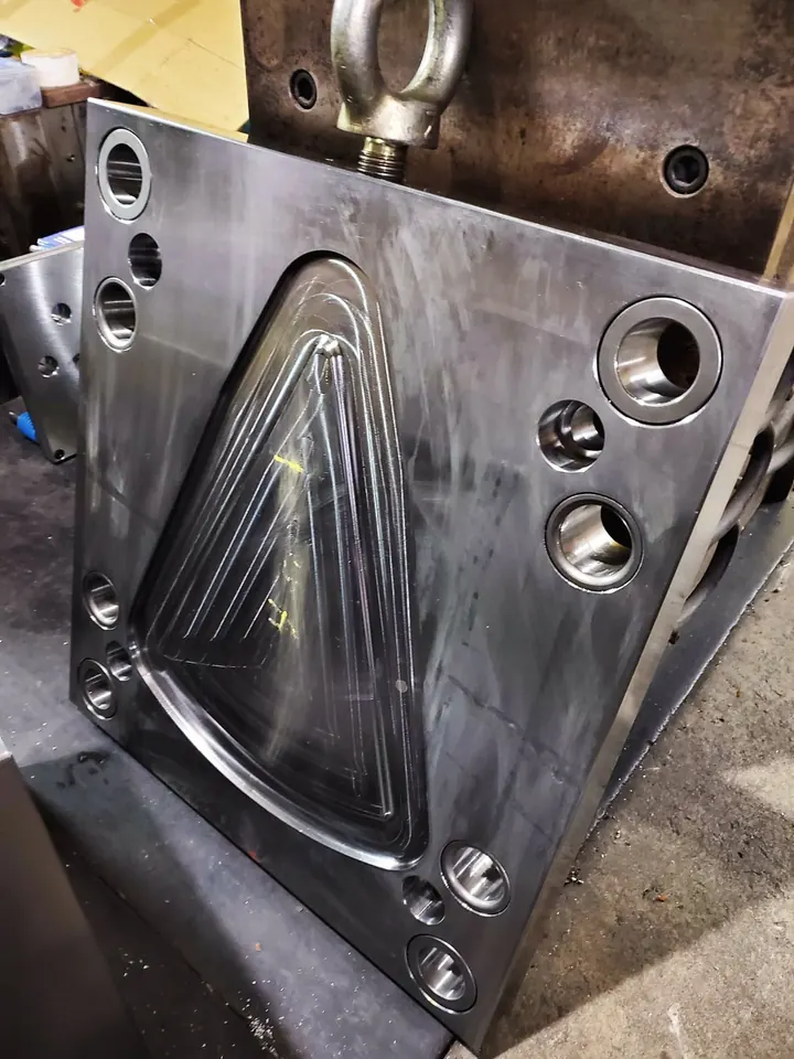
Reaching cores: baffles, bubblers, thermal pins and copper
- Baffle. A hole drilled up into a core from a main line, split by a thin blade so water goes up one side and down the other. Autodesk recommends a baffle slightly larger than the main channel so the blade blocks it fully.
- Bubbler. The blade is replaced by a small tube; water rises inside and falls around it. Autodesk calls bubblers particularly effective for slender cores.
- Thermal pin. A sealed tube with a fluid that boils at the hot end and condenses at the cool end. Autodesk puts its heat transfer at nearly ten times a copper tube's and warns against an air gap around it.
- High-conductivity inserts. Copper alloy or aluminum inserts pressed into slender cores carry heat back to a cooled base. Copper alloy lasts longer; aluminum is cheaper and softer. In Autodesk's comparison, copper-alloy cores cut warpage at short cycles versus H13 or 420 stainless.
Conformal cooling: what it is and when it pays
Drilled channels can only be straight lines, so on a curved or deep part they sit close to the steel in some places and far away in others. Conformal channels curve to follow the molding surface at a constant depth. They are built by metal additive manufacturing; Autodesk names laser sintering, and Plastics Today reports printed inserts in maraging and stainless steel, typically dropped into a conventionally machined mold base. Autodesk cites cycle reductions of 10% to 40%. Plastics Today notes that printed round channels come out with a slightly rougher inside surface, which can add turbulence.
Conformal cooling tends to pay when:
- The part has deep cores, tall bosses or curved walls that drilled lines cannot follow.
- Cooling is clearly the slowest slice of a long-running, high-volume job, so seconds saved add up; see cycle time drivers.
- Warp from a hot core is the problem and baffles or copper inserts cannot reach it.
- Only one or two inserts need it, so the rest of the tool stays conventional.
It usually does not pay on flat, shallow parts that drilled lines already cool evenly, on short runs, or where the extra insert cost outweighs the cycle saving. That trade sits alongside the other tool choices in mold cost drivers and aluminum vs steel tooling; the mold steel selector covers the insert-material side.
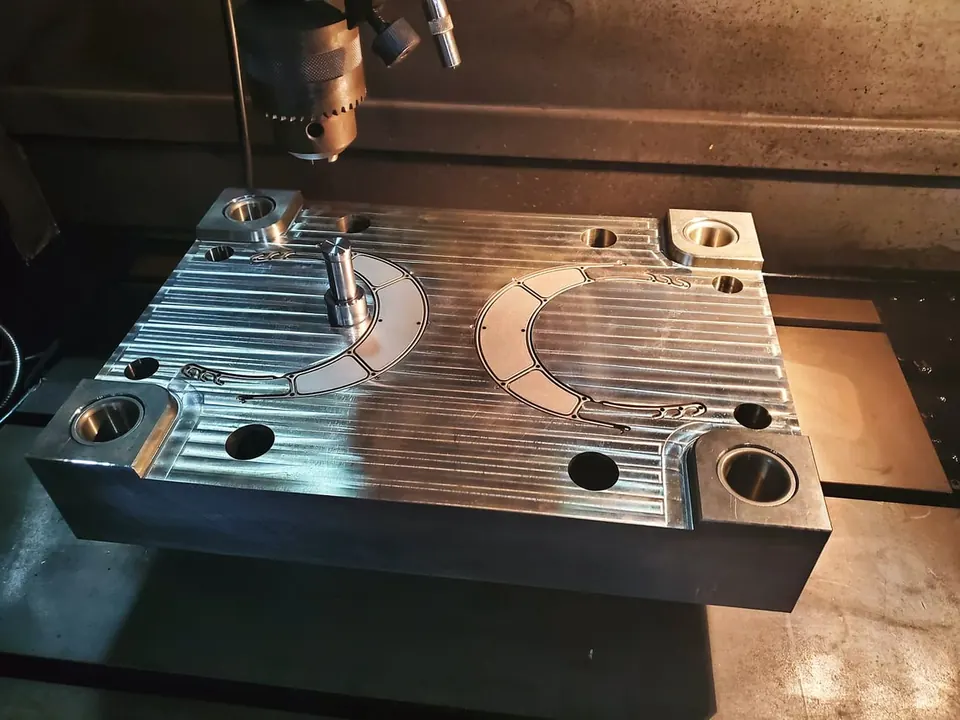
What degrades cooling in production
Scale and corrosion coat the channels and slow heat transfer; Autodesk shows that even small mineral deposits in the lines can significantly lengthen cooling time. Its advice is corrosion-resistant circuit materials, treated or filtered water and regular line cleaning. It also recommends keeping inlet and outlet hookups the same every time the mold is set, and mapping surface temperatures at setup as a benchmark. A mold that ran well last year and now warps parts is often a cooling-water problem before it is a steel problem, part of protecting your tooling.
Questions to ask at tool design review
- Where are the lines on both halves, at what diameter, pitch and depth?
- How are tall cores and bosses cooled: baffles, bubblers, thermal pins or copper inserts?
- Is each circuit in series, and how many circuits are there per half?
- Was a cooling or warp simulation run, and what core-to-cavity difference did it show?
- Are the circuits labeled on the mold with in and out ports, so setup is repeatable?
Common questions
What is the difference between a baffle and a bubbler?
Both carry coolant up into a core from a main line. A baffle splits a drilled hole with a flat blade so water flows up one side and back down the other. A bubbler uses a small tube instead: water rises inside the tube and spills back down around it. Bubblers suit slender cores; baffles suit larger ones.
How much faster is a mold with conformal cooling?
Autodesk cites cycle reductions of about 10 to 40 percent, and the gain depends heavily on the part. Deep cores and curved walls that drilled lines cannot reach benefit most. A flat, shallow part that is already cooled evenly may gain little, so a cooling simulation is the honest way to estimate it.
Why does uneven mold cooling cause warp?
The hotter area of the mold lets the plastic next to it cool later and shrink more. When one half or one region runs hotter, the part shrinks unevenly and bends as it finishes cooling. Keeping core and cavity within a few degrees of each other is one of the main ways a tool prevents warp.
Can an existing mold be upgraded with better cooling?
Sometimes. Extra drilled lines, baffles or a copper-alloy insert can be added if there is steel left between the cavity, ejector pins and screws. Replacing a core with a printed conformal insert is also possible on some tools. It is a tool change, so it needs a design review first.
Does the mold need chilled water or tower water?
It depends on the mold temperature the resin needs. Some resins run with cool water, others need heated water or oil to keep the mold hot. The resin datasheet gives the mold temperature range, and the cooling circuits are set up to hold that temperature evenly, not simply as cold as possible.
Sources
- MoldMaking Technology (Hasco) - Fundamentals of Designing the Optimal Cooling System
- Autodesk - 11 Factors for Efficient Mold Cooling
- International Journal of Heat and Mass Transfer (2021) - Design and fabrication of conformal cooling channels in molds: Review and progress updates
- Plastics Today - New 3D Printing Technologies Accelerate Injection Molding Operations
Send the part file and the quantity you expect to run, and we'll review it before you commit to tooling. NDA first if you want one.
Send a part for reviewBook a 30-minute call