What sets the cycle time of an injection-molded part?
A cycle is fill, pack and hold, cooling, then open, eject and close. Cooling usually takes the largest share, often more than two-thirds, and it grows with the square of the thickest wall. So the part designer sets most of the cycle; the mold's cooling and the press settings decide how close production gets to that limit.
The four slices of a cycle
Every shot repeats the same sequence: the screw fills the cavity, keeps pressure on while the plastic packs and the gate freezes, the part sits in the closed mold until it is stiff enough to push out, and then the mold opens, ejects and closes again. The screw recovers the next shot while the part is cooling, so recovery normally hides inside the cooling slice unless the shot is very large.
| Slice | What sets its length | Who mostly controls it |
|---|---|---|
| Fill | Shot volume, flow length, wall thickness, gate size, resin viscosity, press speed | Designer and toolmaker (geometry, gate); molder (speed) |
| Pack and hold | Time until the gate freezes so no more plastic can enter | Toolmaker (gate size); molder (hold profile) |
| Cooling | Thickest section, resin, melt and mold temperature, how well the steel is cooled | Designer first, then toolmaker; molder sets the timer |
| Open, eject, close | Mold opening stroke, slides and lifters, ejection, robot pick, press speed | Toolmaker and press choice |
Of the four, cooling dominates. Autodesk's mold-cooling guide says cooling can account for more than two-thirds of total cycle time for thermoplastic parts. BASF's technical note on estimating cooling times opens with the same point: most of the injection molding cycle is taken up by cooling. That is why almost every serious cycle discussion turns into a wall-thickness discussion.
Why thickness wins
Heat leaves the part by conduction into the steel, and the middle of the wall is the last place to cool. In the cooling-time equation for a flat wall, the thickness term is squared. BASF reduces it to a simple rule for comparing two walls of the same resin under the same conditions: the cooling time for the second wall equals the first one multiplied by (s2 / s1) squared. Celanese's Vectra design guide states it the same way, that cooling time changes approximately with the square of the wall thickness, and RJG's training note calls thickness the term with the most influence because it is squared. BASF adds a detail that matters for tool design: the heat to remove falls only in proportion to thickness, so a thinner wall needs the mold to pull heat out faster per second to actually reach its shorter cooling time.
The part is ready when it is stiff enough to eject without distortion. RJG notes the ejection temperature used in the estimate is typically the resin's heat deflection temperature or slightly below it. The cycle time calculator puts melt, mold and ejection temperatures and the resin's diffusivity into the full equation if you want an absolute number rather than a ratio.
Worked example: one thick spot
A hypothetical polypropylene housing has a 1.8 mm nominal wall. Assume a trial on a similar part established fill at 1.0 s, then 8.0 s of cooling with the mold closed (pack and hold run inside that time), and 5.0 s to open, eject and close. That is a 14.0 s cycle, or 3600 / 14.0 = 257 shots an hour.
Now the design adds a solid mounting pad that is 3.0 mm thick. The pad, not the nominal wall, decides when the part can be ejected without the pad bulging or sinking. Using the square rule: 8.0 x (3.0 / 1.8) squared = 8.0 x 2.78 = 22.2 s. The cycle becomes 1.0 + 22.2 + 5.0 = 28.2 s, or 128 shots an hour. In a four-cavity tool, that is the difference between roughly 1,030 and 510 parts an hour from the same press. Coring the pad out to the 1.8 mm wall with ribs brings the cycle back to about 14 s and also removes the sink risk described in sink marks.
Two cautions on the arithmetic. The square rule holds for the same resin, melt and mold temperatures and a flat-wall shape; corners, bosses and core pins that run hot cool slower than it predicts. And a trial on the real tool is always the final word.
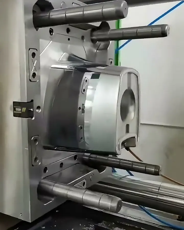
What a designer controls
- The thickest section. Keep walls uniform and core out pads, bosses and rib roots; see wall thickness.
- Resin choice. Different grades need different mold temperatures and eject at different temperatures. Autodesk notes cycle time is most influenced by changes in mold temperature, and a resin that needs a hot mold for gloss or crystallinity cools slower.
- Features that slow the mold down. Undercuts that need slides or lifters, unscrewing threads and deep draws lengthen the open-eject-close slice.
- Cosmetic demands. A high-gloss or low-stress requirement can force a hotter mold and a longer cycle.
What the tool and process control
The toolmaker decides whether the steel can actually remove heat at the rate the wall allows: channel layout, baffles in cores, copper-alloy inserts in hot spots, all covered in mold cooling. Gate size sets when the gate freezes and so the hold time. Cavity count multiplies output without changing the cycle, which is the trade in single vs multi-cavity tooling. On a cold-runner tool, a thick sprue or runner can become the slowest-cooling section, so runner size matters too. The molder then sets the timers, temperatures and robot motion within those limits.
What goes wrong when the cycle is pushed
- Ejecting too warm: pin pushes, distortion and warp that appears later. See why parts warp.
- Cutting hold time below gate freeze: sinks, voids and part weight that varies shot to shot.
- Running the mold colder for speed: poorer surface, higher molded-in stress, and on some semi-crystalline resins, more shrink after molding.
- Quoting a cycle the tool cannot hold: if the price assumed 14 s and the part needs 28 s, someone loses money or quality. Ask how the quoted cycle was estimated.
When the answer changes
On very thin parts, such as packaging lids, cooling shrinks so much that fill speed and mold movement become the limit, and press speed or robot design is where time is saved. On very thick parts, cooling can be so long that a different process, like the methods in structural foam and gas assist, or a redesign with ribs, pays off faster than any tool improvement.
Common questions
What is a typical injection molding cycle time?
It ranges from a few seconds for thin packaging parts to well over a minute for thick or large parts. For a given resin, wall thickness is the best predictor, because cooling time rises with the square of the thickest section. A useful estimate comes from the resin, the thickest wall and the mold temperature, then a trial confirms it.
Does adding cavities make the cycle longer?
Usually only slightly, if at all. More cavities need a larger shot and sometimes a longer fill, but the cooling of each part is about the same. That is why multi-cavity tools lower part cost: the output per hour rises nearly in step with the cavity count while the cycle stays similar.
Can a molder shorten the cycle without changing the tool?
Somewhat. Tuning mold temperature, hold time and mold movement can trim time, but cooling cannot go below what the thickest section and the tool's cooling allow without risking warp, sink or pin marks. Large gains usually come from design changes, better tool cooling or more cavities.
Why does a thin-walled part sometimes not cycle faster?
Thin walls cool quickly, but the mold has to remove heat faster to take advantage, and fill, hold and mold movement become a bigger share of the cycle. If the tool's cooling is poor, or the part has slides and a robot pick, those slices limit the cycle instead of wall thickness.
How does cycle time affect part price?
Press time is usually billed by the hour, so the part's share is the cycle divided by the number of cavities, plus material and handling. Doubling the cycle roughly doubles the machine portion of the price. The cost per part calculator shows how cycle, cavities and resin combine.
Sources
- BASF - Estimating cooling times in injection molding (technical information)
- Autodesk - 11 Factors for Efficient Mold Cooling
- RJG - How to Determine Injection Molding Cooling Time
- Celanese - Vectra LCP Design Guide (cooling time and wall thickness)
Send the part file and the quantity you expect to run, and we'll review it before you commit to tooling. NDA first if you want one.
Send a part for reviewBook a 30-minute call