How do you design a snap fit for a molded plastic part?
Pick the snap type, then size the arm so the strain at its root stays under the resin's published limit (about 60% of it if the joint is opened often). Set the lead-in and retention angles from friction, and decide how the mold releases the hook: a window under it, a slide, or a lifter.
A snap fit is a molded hook or bead that bends out of the way during assembly and springs back behind a ledge on the mating part. It has to pass three checks: the arm bends that far without cracking, the push to fit and the pull to remove suit the product, and the tool can form the hook. Designers usually settle the first two in CAD and only meet the third when the mold design comes back with a slide in it.
Choose the snap family first
Resin suppliers group snap joints into a few basic shapes, and each one loads the plastic differently:
- Cantilever. A beam with a hook on its tip, loaded in bending. This is the workhorse for housings, battery doors and covers. A U-shaped arm is a cantilever folded back on itself to get more length into a short space.
- Torsion. A rocker arm on a molded torsion bar; pressing one end lifts the hook, so the latch releases by hand. The bar carries shear rather than bending.
- Annular (cylindrical). A continuous bead around a round part, like a pill-bottle cap. DuPont notes these are generally stronger than cantilever lugs but need more assembly force, and the part comes off the core by being stripped, so the resin has to recover well from that stretch.
Two details from Covestro's (formerly Bayer) snap-fit guide matter early. An annular joint designed to be inseparable needs a split-cavity mold, so it is best avoided. And when both mating parts flex equally, each sees roughly half the strain, so the undercut can be about twice as deep as when one part is rigid.
The strain check, worked through
For a straight cantilever of constant section, BASF and Covestro both give the strain at the root as about 1.5 × t × y ÷ L², where t is the arm thickness, y the undercut it must clear and L its length. Length is squared, which is why shortening an arm late in a design is the classic way to crack it.
Worked example. A polycarbonate cover uses a straight arm 10 mm long and 1.2 mm thick that must clear a 0.9 mm undercut. Root strain = 1.5 × 1.2 × 0.9 ÷ 10² = 1.62 ÷ 100 = 1.6%. Covestro lists 4% as the short-term limit for unreinforced polycarbonate in a single assembly and says to use about 60% of that, 2.4%, if the joint is opened often. At 1.6% the arm passes both. Cut the same arm to 8 mm and the strain becomes 1.62 ÷ 64 = 2.5%: still fine for one-time assembly, now over the limit for a cover that gets opened for service.
Two corrections to keep in mind. Tapering the arm so it ends at half its root thickness raises the permissible deflection by more than 60%, per Covestro. And for short, stubby arms the wall the arm grows from flexes too; BASF's study found the simple formula underestimates the deflection, and in its own worked example an arm with a length-to-thickness ratio of 5 gets a correction factor of 2.0, which halves both the computed strain and the holding force. The snap-fit cantilever calculator runs the forces once the strain is settled.
| Resin family | Short-term strain limit, single assembly | Where the number comes from |
|---|---|---|
| Polycarbonate, unreinforced | 4% | Covestro table, 23 °C |
| PC/ABS blend | 2.5% | Covestro table, 23 °C |
| Polycarbonate, 10% glass | 2.2% | Covestro table, 23 °C |
| Polycarbonate, 20% glass | 2.0% | Covestro table, 23 °C |
| Semi-crystalline resins (PP, POM, nylon) | close to the yield strain | Covestro rule of thumb |
| Amorphous resins (ABS, PC) | about 70% of the yield strain | Covestro rule of thumb |
| Glass-filled, no clear yield point | about half the elongation at break | Covestro rule of thumb |
These are typical values and vary by grade; the guide for the exact grade overrides them. For any joint that is separated and rejoined, take about 60% of the single-assembly figure.
Lead-in angle and retention angle do different jobs
The push needed to assemble, and the pull needed to separate, both equal the arm's bending force multiplied by (μ + tan α) ÷ (1 − μ tan α), where α is the face angle and μ the friction coefficient. Friction is not small for plastics: Covestro lists 0.45–0.55 for polycarbonate and 0.50–0.65 for ABS sliding on steel, and says the same plastic on itself runs higher, by about 1.2 times for those two. Acetal, at 0.20–0.35, is far slicker.
Take the polycarbonate cover with μ = 0.6 (plastic on plastic). A 30° lead-in gives a multiplier of (0.6 + 0.577) ÷ (1 − 0.6 × 0.577) = 1.8. A 45° retention face gives (0.6 + 1) ÷ (1 − 0.6) = 4.0, so the cover takes a bit over twice as much pull to remove as push to fit. Steepen the retention face past the angle whose tangent is 1 ÷ μ, about 59° here, and the denominator goes to zero: the joint locks, and only deflecting the arm by hand or tool will open it. Lubricated or slicker resins move that lock-up angle higher, so a permanent latch in acetal needs a face much closer to 90°.
What the hook does to the mold
The hook is an undercut: the retention face points against the direction the mold opens. Something in the tool has to get out from under it. The options, from cheapest to most involved:
- Pass-through core (sliding shutoff). Leave a window in the wall directly below the hook. Core steel comes up through the window, forms the underside of the hook and pulls straight out. Protolabs calls this probably the best way to make clips, but it needs the hook aligned with the mold opening, a relief hole the product can live with, and sometimes extra draft on the shutoff faces. BASF gives the same advice: a slot under the snap ledge, or a snap placed at the outside edge of the part, removes the need for slides.
- Side action or lifter. If no window is allowed, a slide moving at right angles to the pull, or an angled lifter on the ejector side, forms the undercut and moves clear before ejection. Each one is moving steel that adds to what drives the cost of an injection mold and to maintenance.
- Hand-loaded insert. A loose steel piece placed and removed each shot. Workable for low volume, slow for production.
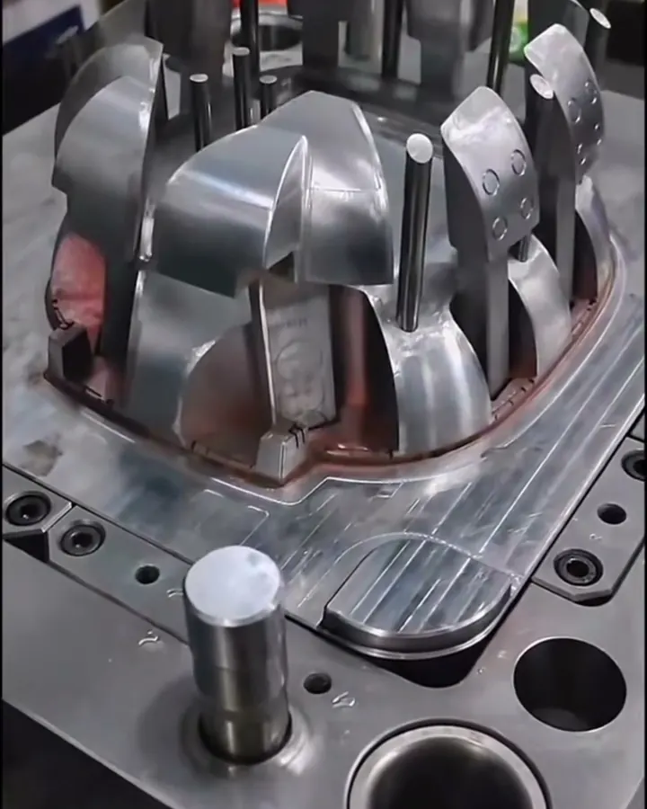
Hooks inside a box lid, facing inward, usually end up on lifters; hooks on the outer edge often clear with a pass-through. If you are still choosing where the latches go, put them where a straight pull can make them. For how the two mold halves divide the work, see what the cavity and core are, and keep normal draft on the arm's side faces so it ejects cleanly.
How snap fits fail
- Root crack. The formula already puts peak strain at the root; an unradiused corner there multiplies it. Give the root a generous radius.
- Arm left under load. Covestro's guide says the features should return to a stress-free state after assembly. An arm parked half-deflected because of tolerance stack-up will creep and lose its grip.
- Rattle and low hold. BASF lists clearance from tolerance stack-up and low pull-away force as built-in limits of snaps. Allow for the worst-case stack, or add a crush rib.
- Wrong resin. Protolabs points out that a flexible resin like ABS makes a better clip than acrylic or PEEK. Brittle grades need longer, tapered arms or a different joint.
Checklist before the tool is cut
- Snap family chosen, and whether the joint is assembled once or opened often.
- Root strain calculated against the grade's limit, using 60% of it for service joints.
- Lead-in and retention angles set from friction, with the lock-up angle known.
- A pass-through window agreed with industrial design, or the slide or lifter accepted.
- Root radius, draft and gate location set so the flow does not meet at the root.
- Assembly and pull tests planned on molded parts at the coldest service temperature.
When a snap is the wrong answer
If the joint has to clamp a gasket evenly, carry a steady load for years, or be opened dozens of times, use screws: see how to design screw bosses. If it must be permanent and sealed, look at welding in the ways to join two molded parts. A molded living hinge on one side and a single snap on the other is often the simplest closure of all.
Common questions
What strain can a snap-fit arm take?
It depends on the resin and on how often the joint is used. Covestro lists 4% for unreinforced polycarbonate and 2.5% for PC/ABS for a single assembly at room temperature. For joints that are opened and closed repeatedly, design to about 60% of the single-assembly value.
Do snap fits need a slide in the mold?
Not always. If the hook faces the mold-opening direction and the product can have a small window in the wall under the hook, core steel can pass through that window and form the hook with a straight pull. If no window is allowed, a slide or lifter is usually needed.
How do I make a snap fit permanent?
Make the retention face steep enough that friction alone holds it. Once the tangent of the retention angle reaches 1 divided by the friction coefficient, no straight pull will lift the hook; only bending the arm by hand or with a tool releases it. For plastic on plastic with friction around 0.6 that is near 59 degrees; slicker resins need a steeper face.
Why did my snap-fit arm crack at the base?
The base of a cantilever carries the highest strain, and a sharp inside corner there multiplies it. Common causes are an arm shortened late in the design, a root with no radius, a weld line at the root, or a brittle or dry grade. Lengthen or taper the arm and radius the root.
Is a tapered snap arm better than a straight one?
In most designs. Thinning the arm so its thickness tapers to half at the hook spreads the bending along its length, and Covestro reports it allows more than 60% more deflection than a straight arm at the same strain. It is a small change in the CAD and costs nothing in the mold.
Sources
- Bayer MaterialScience (now Covestro) - Snap-Fit Joints for Plastics: A Design Guide (copy hosted on an MIT course site)
- BASF - Design Solutions Guide (Part V, Snap-Fit Assembly) (copy hosted by hankyan.com)
- DuPont - General Design Principles for DuPont Engineering Polymers, Module I (snap-fits) (copy hosted by Distrupol)
- Protolabs - 5 Ways to Master Complex Features in Injection-Molded Parts
Send the part file and the quantity you expect to run, and we'll review it before you commit to tooling. NDA first if you want one.
Send a part for reviewBook a 30-minute call