What does a mold flow analysis tell you, and is it worth doing?
A mold flow analysis simulates how plastic fills, packs, cools and warps in a proposed tool, so gate, wall and cooling mistakes show up on a screen instead of on the first samples. Its fill and pressure results are dependable. Its warp numbers are a comparison, not a measurement. It pays on new, large, glass-filled or tight-tolerance parts.
Four modules in one chain
Most simulation packages (Moldflow, Moldex3D, SOLIDWORKS Plastics and others) split the job into the same four steps. A cool step works out the temperature of the mold surface from the cooling layout. A flow step fills the cavity, tracking how the melt thickens as it cools against the steel, and reports pressure, temperature, short shots and weld lines. A pack step models the holding phase: more material pushed in as the part shrinks and freezes, which gives gate freeze, hot spots, volumetric shrinkage and a cycle estimate. A warp step then takes the residual stress left by fill and pack and predicts the shape of the part after ejection and cooling.
That order matters when you read the results. Fill comes before pack and warp, so it carries the fewest assumptions and is the result most worth trusting. Warp is the last link, so it carries every assumption made upstream.
What each result is good for, and where to be careful
| Result | What it tells you | Use it for | Be careful with |
|---|---|---|---|
| Fill pattern / flow front | Where the melt goes first and last, short shots, air traps, weld lines | Gate position, vent locations, moving a weld line off a cosmetic face | Weld-line strength. It shows where lines form, not whether they crack |
| Injection pressure and clamp force | Whether the press can fill the part, and at what force | Wall decisions, gate count, press size | Absolute values. They move with the melt temperature and fill time the molder actually runs |
| Pack and volumetric shrinkage | Under-packed zones, sink and void risk, when the gate freezes | Rib and boss proportions, gate size | Exact sink depth on a cosmetic face |
| Cooling | Hot spots, uneven mold-surface temperature, time to freeze | Cooling-line layout, spotting thick sections that set the cycle | Treating the cycle estimate as a quoted number |
| Warp / deflection | Direction and size of distortion, split by cause | Ranking gate or design options against each other | Absolute flatness against a tight drawing tolerance |
The most useful warp output is often the breakdown, not the total. A good analysis separates deflection into orientation effects, differential shrinkage across the part, and differential cooling between the two mold halves. Each cause has its own lever: gate location or flow leaders for orientation, wall layout and packing for differential shrinkage, and the cooling layout for uneven mold temperature. The mechanisms are covered in why molded parts warp; the simulation's job is to tell you which one is in charge on your part.
The inputs that decide whether the answer means anything
- The mesh type has to fit the geometry. Autodesk's guidance is that a midplane mesh suits parts that are thin-walled throughout, and a dual-domain (surface) mesh suits mostly thin parts where each local region is at least four times longer and wider than it is thick, with ten times as the safer figure. Chunkier regions call for a 3D mesh. Autodesk also says a dual-domain mesh match below 80% is a reason to switch to 3D.
- Material data for the exact grade. A family name like "PC/ABS" isn't an input. Warp in particular needs more than viscosity: dual-domain warp uses measured shrinkage data where it exists, and 3D warp uses pressure-volume-temperature data plus mechanical and thermal-expansion properties. If the grade in the database lacks them, the warp result rests on generic values. Glass-filled grades are the sharpest case because fiber orientation sets shrinkage in and across the flow; see glass-filled resins.
- Process settings a real press will run. Fill time, melt and mold temperature, the switchover point and the pack-pressure profile should match the molder's plan, not the software defaults.
- The real runner and cooling layout. Some tools let you skip the cooling step and type in one uniform mold temperature. That runs faster, but it hides exactly the hot spots a cooling analysis exists to find.
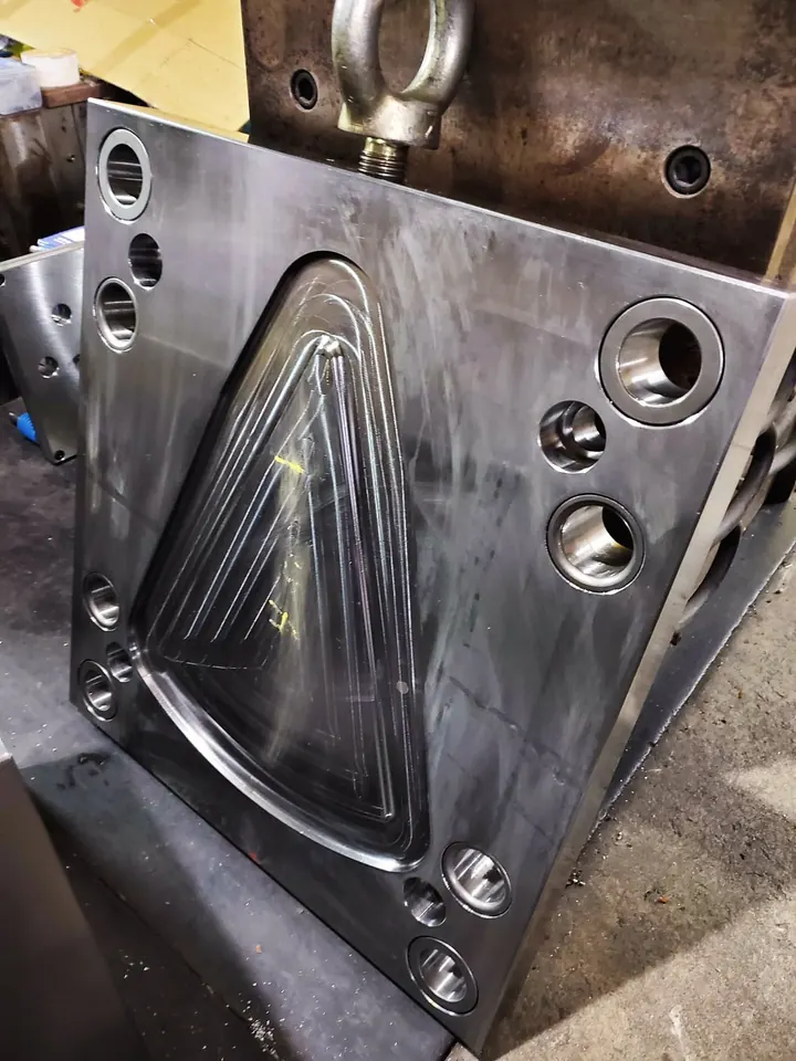
Worked example: a 2.5 mm ABS cover
Take a hypothetical ABS cover, 220 mm long and 100 mm wide, with a 2.5 mm nominal wall. That sits inside the 1.14 to 3.56 mm range Protolabs lists for ABS, so the wall itself isn't the problem. The first proposal is a single edge gate at one end.
- Mesh check. The main wall is 100 mm wide against 2.5 mm thick, a ratio of 40, so dual domain is fine there. But the cover has four screw-boss pads 6 mm thick and 15 mm across. That's a ratio of 2.5, under the factor-of-four line, so either those regions get a 3D mesh or you accept that the boss results are rough.
- Pressure check. Suppose the fill run reports a peak of 118 MPa and the press the molder intends to use can deliver 160 MPa at the nozzle, the low end of the 160 to 300 MPa range Autodesk's help gives for typical machines. That is 74% of capacity. It fills on paper, but the last quarter has to cover a stiffer resin lot, a cold mold and any runner or nozzle losses the model left out.
- Re-gate. Moving to a center gate roughly halves the flow length to about 110 mm. Suppose the re-run now shows 82 MPa, about 51% of capacity. The trade is a weld line on the far side of a center opening, so check where it lands against the cosmetic face and any snap or screw load.
- Warp comparison. Suppose the edge-gated version predicts 0.9 mm of bow along the length with orientation as the largest contributor, and the center-gated version predicts 0.4 mm. Read that as "center gating is clearly better and orientation is the lever," not as "the part will measure 0.4 mm." The real number comes off the first samples.
The example shows the pattern: fill and pressure results justify a gate decision on their own, while warp is best used to rank options.
Reading a report without getting snowed
- Check the first page: exact resin grade, melt and mold temperature, fill time. If they don't match the molding plan, the rest is a different part.
- Check the mesh type and, for dual domain, the mesh-match figure.
- Watch the fill animation. The last place to fill should be at a vent or parting line, not trapped in a blind pocket. Hesitation at thin sections is an early short-shot warning.
- Compare peak pressure at switchover with the actual press, not a generic one.
- Find every weld line and ask whether it sits on a load path or a show surface.
- Look at the spread of volumetric shrinkage around ribs and bosses; big local spikes are where sink marks start.
- For warp, check the plot's exaggeration factor, ask for the cause breakdown, and ask that deflection be measured from the same datums your drawing uses.
When it pays and when to skip it
Usually worth doing: a first production tool for a new part; long, large or flat parts; glass-filled grades; multi-cavity and family tools where fill balance matters (see single vs multi-cavity tooling); thin walls near the limit of the resin; tight flatness or fit tolerances; and any mold where recutting steel would hurt.
Often skippable, or fill-only: a small, simple part close in shape and resin to one already running well; a soft prototype tool that will be modified anyway (see prototype vs production tooling); or a grade with no characterized data, where a fill-only run still checks gating and pressure but a warp run would be guesswork.
There's a middle path most buyers overlook. A fill-only run answers gate, vent, weld-line and pressure questions cheaply. Save the full fill-pack-cool-warp study for parts where distortion is the real risk. And run it before steel is cut: the analysis is cheapest when the gate can still move anywhere. For a first-pass sense of press size from projected area, the tonnage calculator is a quick cross-check on the clamp-force result, and wall thickness is the input most worth getting right before any simulation runs.
Common questions
Is mold flow the same thing as Moldflow?
Moldflow is Autodesk's product name. People use it loosely for any injection molding simulation, which also includes Moldex3D, SOLIDWORKS Plastics, Sigmasoft and others. The four basic steps of cooling, filling, packing and warp are common to all of them, so ask which package and mesh type was used rather than assuming.
How accurate is a mold flow warp prediction?
It depends on the material data and the mesh. With complete data for the exact grade and a mesh that suits the geometry, warp predictions are good at showing direction, cause and which design option is better. Treat the absolute value as an estimate until first samples are measured, especially for glass-filled grades where fiber orientation drives shrinkage.
Who should run the analysis, me or the toolmaker?
Whoever runs it needs the final part model, the exact resin grade, the planned gate and runner layout and the cooling design. That usually points to the mold designer, with you reviewing the report. If you commission it separately, make sure the analyst and the toolmaker agree on the gate location and process settings first.
Can mold flow help after the mold is already built?
Yes. Simulation is often used to troubleshoot a part that warps or short-shots on the first samples. Splitting the warp into orientation, differential shrinkage and cooling causes can point to the fix faster than trial and error at the press, and lets you test a gate or cooling change before cutting steel.
Does a mold flow analysis replace a DFM review?
No. A design for manufacturability review checks draft, undercuts, wall transitions, tolerances and how the tool will be built. Mold flow answers narrower questions about filling, packing, cooling and distortion. The two work together: the DFM review sets the geometry, and the simulation tests whether that geometry will mold the way you expect.
Sources
- Dassault Systemes - SOLIDWORKS Plastics Help: COOL, FLOW, PACK, and WARP modules
- Autodesk - Moldflow Insight Help: Mesh types
- Autodesk Support - How to know when to use dual domain or 3D mesh in Moldflow
- The Madison Group - Using Computer Simulation to Solve Warpage Problems
- Protolabs - Design Guidelines: Plastic Injection Molding
- Autodesk - Moldflow Help: Injection pressure result
Send the part file and the quantity you expect to run, and we'll review it before you commit to tooling. NDA first if you want one.
Send a part for reviewBook a 30-minute call