What causes a short shot in injection molding, and how is it fixed?
A short shot is a part the melt didn't finish: a rounded rib tip, a missing corner, a latch that never formed. There are three causes. Not enough plastic reached the cavity, the melt froze before it got to the end, or trapped air or a restriction in the tool held it back. Planned short shots show which.
The best evidence is the edge where the plastic stopped. On a true short shot it is smooth, glossy and rounded, because that was the flow front at the moment it froze, and its position tells you where the melt ran out of heat, pressure or room. Before anyone changes a setting, keep that part, note which cavity and which shot it came from, and weigh it next to a full one.
Is it really a short shot?
Check it against the defects it gets confused with on first samples, because each one has a different fix:
- Short shot: the outline of the part is incomplete. Steel was there to form a feature, and no plastic reached it. Weigh it against a good part and it is lighter.
- Sink: the outline is complete, but the surface has a shallow dent, usually opposite a thick rib or boss. The plastic arrived and then shrank away from the steel as it cooled. That is a packing and wall-thickness problem, covered in sink marks.
- Hesitation short: a thin feature close to the gate is missing, while the far end of the part is full. Autodesk's Moldflow help explains why: the melt runs preferentially into thicker sections, and the melt that stalls in the thin one loses heat while the rest fills. By the time pressure turns toward it, it has frozen.
- Short with a burn at the edge: a brown or black scorch right at the unfilled edge means air was trapped there and compressed ahead of the melt. That is a vent problem first; how mold vents work covers it.
Three ways a cavity ends up short
Every short shot reduces to one of three stories: not enough plastic reached the cavity, the plastic froze before it got to the end, or something in the tool held it back. The lists in troubleshooting guides are long, but each item belongs to one of these.
| Cause | What the melt is doing | Fix that matches it |
|---|---|---|
| Too little material or shot size | The first stage stops before the cavity is full, or melt slips back past the check ring, so the part comes out light with little or no cushion left. | Raise the shot size or move the transfer position later; confirm a steady cushion and test the non-return valve if it wanders. |
| Injection pressure or speed too low | The press cannot hold the set speed, so the flow front loses momentum and the skin freezes before the melt reaches the end. | Raise injection pressure and speed, and confirm the press is large enough to deliver them for the shot. |
| Melt or mold too cold | Cold steel or a stiff, cold melt grows the frozen skin faster than the front advances, narrowing the channel until flow stops. | Raise melt and mold temperature so the melt stays fluid over the whole flow length. |
| Gate or runner too small | A small gate, a long or narrow runner, or a lodged cold slug spends pressure before the melt ever reaches the part. | Open up the gate or runner to the size a fill study supports, and clear any cold slug at the gate. |
| Trapped air, poor venting | Air at the last place to fill is compressed into a pocket the melt cannot push through, often leaving a burn at the edge. | Add or clean vents at the last-to-fill points, including deep ribs and blind pockets far from the parting line. |
| Thin wall or long flow length | The flow ratio (flow length divided by wall thickness) is too high for the resin, so a thin rib or a far corner stays short. | Cut the flow ratio: thicken the path slightly, add a flow leader, or move the gate closer to the feature. |
1. Not enough melt delivered
This is the machine side. The shot size or the transfer position is set so the first stage stops too early. Or the process needs more injection pressure than the press can give, so the screw can't hold the set speed and the front freezes on the way. Robert Gattshall, writing in Plastics Technology, calls these pressure-limited shorts, and gives a common route into them: melt temperature is lowered to stop flash, the melt gets stiffer, and the pressure it needs climbs past what the machine has. Or the melt goes the wrong way. The non-return valve at the tip of the screw (the check ring) should close when the screw moves forward. Gattshall lists two failures: a valve that does not seal, so plastic flows back along the screw during injection, and a bit of debris that props the valve open. The second one produces shorts that come and go, which is what makes it hard to find.
The giveaway is the cushion, the small reserve of melt left in front of the screw at the end of injection. John Bozzelli, also in Plastics Technology, puts the allowable shot-to-shot variation at about 1 mm either way. A cushion that drifts toward zero means the screw is bottoming out, and a bottomed screw has nothing left to push with.
2. The melt freezes before it gets there
Molten plastic touching cooler steel forms a frozen skin at once, and the channel the rest of the melt flows through narrows as it travels. Whether the front reaches the end depends on how far it has to go, how thin the channel is, and how runny the melt is. Viscosity rises when melt or mold temperature is low, when a stiffer or more heavily filled grade replaces the one the tool was designed for, or when a lot is out of its normal flow range. Injection speed matters too: a slow fill gives the skin more time to grow.
The geometry part has a number. Michael Hansen of Mack Molding, writing in Medical Design Briefs, defines flow ratio as the distance the melt travels divided by the wall thickness, and says that where the wall changes along the path you add up the ratio for each segment. A long path through a thin wall gives a high ratio; so does a thin rib at the far end of an otherwise normal wall. The acceptable ratio depends on the resin. Hansen notes that suppliers often don't publish an ideal value, which is why spiral-flow tests and fill simulation are used to judge it.
3. The tool holds it back
A small gate, a long or narrow runner, a hot runner nozzle that has frozen, or a cold slug lodged in a gate all spend pressure before the plastic reaches the part. Bozzelli's pressure-loss example in Plastics Technology shows how much: on a small polycarbonate part in a four-cavity tool, the sprue and runner used 12,036 psi of the 29,988 psi in the nozzle, about 40% of it spent before the melt even reached the gates. He also warns against simply opening up the runner, because a fatter runner shears the melt less and so the melt runs thicker; he suggests a fill simulation to find the compromise.
Air is the other tool cause. The cavity is full of air before the shot, and it has to leave through vents at the last places to fill. If a vent is missing, blocked or in the wrong place, the air is compressed into a pocket the melt cannot push through. Deep ribs and blind pockets are the usual spots, because their dead-end bottoms are far from the parting line where most venting is cut.
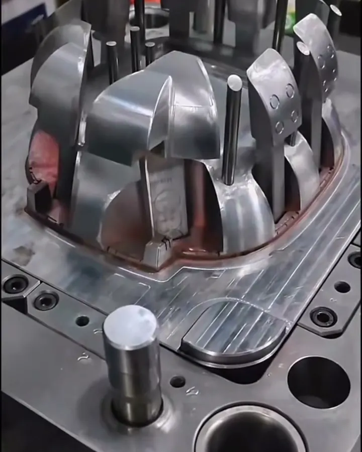
Diagnose it with a short-shot sequence
The quickest way to see what the melt is doing is to stop it on purpose at several points and look. Bozzelli lists more than a dozen reasons molders make deliberate short shots, among them reading the fill pattern, checking balance between cavities and troubleshooting shorts themselves. The sequence below follows his method.
- Take second stage out of the picture. Turn hold pressure down to a very low value but keep some hold time. Bozzelli suggests 5-10 psi on hydraulic presses and 50-100 psi on electric ones, not zero, because nearly every job runs with some hold and you want to see how the press behaves at the switch. Make sure the short parts will eject without sticking in the tool.
- Confirm there is a cushion. If the screw bottoms out, Bozzelli points out, the short shot no longer represents the process.
- Step the transfer position. Make one shot that leaves just a nub past the gate, then partial fills further along, and one that stops at about 90-99% full, which is how Bozzelli sets the first stage in his own method. Keep them in order and label them.
- Read the fronts. An even front that simply stops short of the end says the path is too long for the conditions or a vent is missing at the end. A front that races down a thick section and leaves a thin rib behind is hesitation. In a multi-cavity tool, one cavity lagging the others is a balance problem, not a machine problem; single versus multi-cavity tooling explains why balance matters.
- Test the non-return valve if the cushion wanders. Bozzelli's check: set shot size to 80% of barrel capacity, inject and hold for about 12 seconds, and watch whether the screw creeps forward. Repeat at 60, 40, 20, 10 and 5%. Creep at every size points to a worn valve or barrel; creep only at the small sizes points to wear at the front of the barrel.
- Ask what changed. If the tool used to make full parts, something moved: resin lot, regrind ratio, dryer, a heater band, the valve, a vent packed with residue. Gattshall's view is that a process change should be the last thing you try on a job that used to run.
Worked example: the rib is where it shows, not where it starts
Take a hypothetical lid with a 1.5 mm nominal wall, gated at one end. The far edge is 200 mm from the gate, and on that edge sits a latch rib 1.0 mm thick and 12 mm tall. First samples come back with the rib tip rounded off.
The flow ratio, segment by segment. The wall contributes 200 / 1.5 = 133.3. The rib adds 12 / 1.0 = 12.0. Total: 145.3. The rib is where the short shows, but 133.3 of the 145.3, about 92%, comes from the long path before the melt ever gets there.
Three ways to bring it down:
- Thicken the rib to 1.2 mm: 12 / 1.2 = 10.0, total 143.3. That's a 1.4% reduction, and a thicker rib on a 1.5 mm wall makes sink on the opposite face more likely. The rib design calculator shows how fast that goes wrong.
- Add a flow leader, a slightly thicker channel running from the gate toward the rib. Hansen puts leaders at 10 to 25% thicker than the nominal wall and says going past 25% turns the leader into a gas channel. At 1.8 mm, 20% thicker, and treating the leader as the whole path (a simplification), it becomes 200 / 1.8 = 111.1, total 123.1: a 15% cut.
- Move the gate to the middle of the lid. The longest path drops to about 100 mm: 100 / 1.5 = 66.7, plus 12.0, total 78.7. That's 46% lower, and the latch rib now fills at the end of a short path, which is where Autodesk's guidance says thin ribs belong. The cost is a gate mark on a different face, which has to be acceptable on the drawing.
Now the press side. Suppose the same lid later starts going short on some shots but not others. The screw is 35 mm: its cross-section is π/4 × 35² = 962 mm². A 40 cm³ melt shot needs 40,000 / 962 = 41.6 mm of stroke, and a 6 mm cushion holds 962 × 6 = 5,773 mm³, about 5.8 cm³. The log shows cushion steady near 6 mm, then 4.1, 2.0 and 0.4 mm on the shots that came out short. That is far outside Bozzelli's 1 mm band. The screw traveled 5.6 mm further than normal, about 5.4 cm³ or 13% of the shot volume, and the setting didn't change. That melt didn't end up in the cavity, or the parts wouldn't be short. The first suspect is melt slipping back past the check ring, the failure Gattshall describes; Bozzelli's hold test above confirms or clears it, and if the screw creeps, the screw tip comes out for inspection. If debris is propping the valve open, raising shot size would hide it until the debris cleared, and then the extra plastic would end up as flash. Check the press is the right size for the shot in the first place with the shot size and barrel capacity calculator.
Tool fix or process fix?
| What you see | Where it usually lives | First move |
|---|---|---|
| Same feature short on every shot, from the first trial | Design or steel: flow ratio, gate location, missing vent | Short-shot sequence, then a planned tool change |
| Thin feature near the gate short, far end full | Hesitation: gate position relative to thin sections | Faster fill as a test; gate move or added gate as the cure |
| Short shots that come and go; cushion wanders | Machine: non-return valve, heaters, feed | Valve hold test; don't raise shot size first |
| Short edge with a burn | Tool: trapped air at last-to-fill point | Clean or add vents before touching speed |
| One cavity of several short | Tool: runner balance, a blocked gate or hot-runner tip | Check that cavity's gate; don't tune all cavities for one |
| Started after a resin lot, grade or regrind change | Material: viscosity or moisture | Compare the lot paperwork; dry and retest |
The pattern in the first column matters more than any single setting. A process change can cover a design or tool shortfall, but it narrows the window the job has to run in. The tool-or-process note applies the same test across other defects.
Why the fix can create a new defect
Most of the knobs that fill a short part also push plastic toward the parting line: more shot, more pressure, more speed, hotter melt. Gattshall describes molders swinging between the two defects when they adjust without knowing the cause. Faster fill can also cure a short and leave a burn, because the air has less time to get out. A fill problem that only goes away with every setting near its limit is telling you the tool or the design needs the change.
What to settle before steel is cut
- Work out the flow ratio from the gate to the farthest thin feature, using Hansen's segment method, and compare it with the resin maker's spiral-flow data or a fill simulation. What a mold flow analysis tells you covers what the simulation can and can't predict.
- Keep thin ribs and latches at the ends of flow paths, not beside the gate. Gate types and the gate size calculator help with location and size.
- Check walls for sudden thin sections with the wall thickness checker; the reasoning behind uniform walls is in wall thickness.
- Ask where the vents are and whether deep ribs vent through ejector pins or inserts.
- Confirm the press: shot as a sensible share of the barrel, and enough injection pressure left over after the runner takes its share.
- Name short shots as a defect on the inspection plan and judge first samples against a weighed reference part at first-article review. For other symptoms, the defect troubleshooter ranks likely causes.
Common questions
What is a short shot in injection molding?
It is a molded part that is incomplete because the plastic stopped before filling the cavity. The missing area is usually at the end of the flow path or in a thin feature, and the edge where the melt stopped is smooth and rounded. The part also weighs less than a good one.
Can more hold pressure fix a short shot?
Not reliably. Hold pressure packs plastic into a cavity that is already essentially full, to make up for shrinkage. If the first stage left a feature empty, the melt at the front has often already frozen, so hold pressure cannot reach it. Fix the fill, then set hold.
Why do short shots come and go on the same mold?
Intermittent shorts usually point to something that varies shot to shot: a leaking or jammed non-return valve, a heater band failing, a feed problem at the hopper, or a resin lot with different flow. Watch the cushion and part weight. If both wander, look at the machine before the mold.
Is a short shot the mold maker's fault?
Sometimes. If one feature is short on every shot from the first trial, the cause is often in the design or the steel, such as a long thin flow path, a gate in the wrong place, or a missing vent. If the tool once made full parts and now doesn't, the process, machine or material changed.
Does mold flow analysis prevent short shots?
It catches most fill problems that come from geometry, such as hesitation at thin ribs, unbalanced flow and air traps, before steel is cut. It can't foresee a worn check ring, a blocked vent or a wet lot of resin, so the short-shot sequence on the press is still the test that settles it.
Sources
- Plastics Technology - Good Reasons to Make a Short Shot and How to Do It Right (John Bozzelli)
- Plastics Technology - How to Tell if Your Non-Return Valve Is Leaking (John Bozzelli)
- Plastics Technology - Understanding Pressure Loss in Injection Molding (John Bozzelli)
- Plastics Technology - Don't Get Caught in the Flash-and-Shorts Chase (Robert Gattshall)
- Medical Design Briefs - Plastics Molding: The Path of Least Resistance (Michael Hansen, Mack Molding)
- Autodesk Moldflow help - Avoiding hesitation
Send the part file and the quantity you expect to run, and we'll review it before you commit to tooling. NDA first if you want one.
Send a part for reviewBook a 30-minute call