What causes burn marks (dieseling) on molded parts, and how are they fixed?
Burn marks have two sources. Dieseling is air cornered where the cavity fills last, compressed so fast it gets hot enough to scorch the plastic. Degraded-material burns are melt cooked by heat, shear or hang-up spots before it reaches the cavity. Trapped air needs vents or a slower last stage; cooked melt needs the barrel and hot runner fixed.
A brown or black mark on a molded part is plastic that got too hot. The useful question is where it got too hot. In one case the melt was fine until the last instant of fill, when it ran into a pocket of air it could not push out. In the other, the melt was already damaged when it left the nozzle. The two look alike on a sample tray, but the fixes sit in different places: one is mostly in the steel, the other mostly in the barrel and hot runner. Decide which one you have before anyone changes a setting.
Dieseling or cooked melt: telling them apart
| Clue | Dieseling (trapped air) | Degraded melt |
|---|---|---|
| Where it sits | The last spot to fill: far corners, blind pockets, rib ends, the point where two flow fronts meet | Anywhere along the flow; streaks point the way the melt traveled |
| What it looks like | A compact scorch, sometimes on an edge that is also slightly short | Brown or black streaks, or dark specks scattered through the part |
| Shot to shot | Same place, same cavity, every shot | Comes and goes; often worse after the press has stood idle |
| What moves it | Speed at the end of fill; vent condition | Melt and nozzle temperature, residence time, purging |
Mold-Masters' hot runner troubleshooting guide describes the burn as brown streaks from material overheated by trapped air, the diesel effect, and notes it can lighten the color as well as darken it. Its list of causes then mixes both families: high injection speed and trapped or volatile gas on one side; a failing check ring, high back pressure, friction burning and overheated melt on the other. That is why the clues in the table matter more than any one setting. Silver streaks are a third, separate defect. Splay is gas frozen into the skin, and the same guide starts its splay remedies with the dryer, not the vents.
Acetal is the odd one out. DuPont's Delrin molding guide warns that poor venting on Delrin may leave no visible flaw at all, or only an inconspicuous whitish mark, where other resins show a black burned spot. Its trick for finding the trapped air is to spray the mold with a hydrocarbon or kerosene-based spray, a rust preventative will do, just before injection. Where venting is poor, the spray leaves a black spot. The guide singles out multi-cavity molds as the place this test pays off.
Why squeezed air scorches plastic
Air heats up when it is compressed quickly, because the work goes into it faster than it can shed heat to the steel. Jim Fattori, writing in Plastics Technology, compares it to a diesel engine, which ignites its fuel at a compression ratio of about 20:1, and says the air in a mold can compress enough to superheat and make the resin diesel in the cavity. The size of the effect is easy to estimate. NASA's Glenn Research Center gives the relation for compression with no heat loss: T2/T1 = (p2/p1) raised to the power (γ - 1)/γ, with γ = 1.4 for air.
Take air at 20 °C (293 K) and 1 bar absolute in a pocket the melt is closing off. Squeeze it to 20 bar and the ideal result is 293 x 20^0.286 = 690 K, about 417 °C. At 100 bar it is 1,093 K, about 820 °C. Real air loses some heat to the steel, so read these as upper bounds, then set them beside the melt: DuPont recommends a 215 °C melt for Delrin. The skin that touches that pocket gets hit with heat the resin was never meant to see.
The air doesn't need to be trapped for long, and Fattori's arithmetic shows why even a vented tool can burn at speed. Flow into the mold is the screw's area times its forward speed: his 3 in screw at 4 in/s pushes about 28 in³ of melt per second, and the same volume of air has to leave. Through ten vents half an inch wide and 0.002 in deep, 0.010 in² in all, the air would have to move at 2,827 in/s, about 160 mph. Once the melt flows past a vent, that vent is useless, so the last one still open carries the whole flow; his figure for it is 1,605 mph. Air can't get out that fast, so it stays behind and its pressure climbs.
Not all of the gas is air. Fattori notes that polystyrene gives off very few volatiles while polycarbonate, acetal and PVC give off quite a lot. DuPont says high melt temperature, long hold-up time and hold-up areas in the cylinder make acetal generate more gas than normal, and that fast fill makes the resulting venting problems worse. A melt that is starting to degrade therefore feeds dieseling too, which is how both kinds of burn sometimes turn up on the same part.
Where the air gets cornered
The last place to fill is set by part geometry and gate position, so most dieseling is designed in before the first shot. The usual traps:
- The far end of the flow, especially corners the front reaches after it has already touched the parting line in the middle and sealed the vents there.
- Blind pockets and tall ribs, whose closed ends sit well away from the parting line where most vents are ground.
- Flow junctions. Where two fronts meet around a core, the air between them has nowhere to go. DuPont asks for a vent at every flow junction that forms a weld line, and warns that no venting combined with very fast injection corrodes the tool at the weld lines on Delrin. Weld lines and knit lines covers why those joints are weak to begin with.
- The runner. DuPont also recommends venting the runner system, so less air has to leave through the cavities.
Gate position decides which of these traps exist. DuPont's example is a closed-end tube such as a pen cap: gated at the center of the closed end, the air is swept toward the parting line and vents normally; gated on the side, air is trapped on the opposite side near the closed end. Bob Salhaney of DME, also in Plastics Technology, puts the best vent location opposite the gate, where the part fills last. A fill simulation shows the trap locations before steel is cut; what a mold flow analysis tells you explains which questions it can answer, and gate types covers the options when the gate has to move.
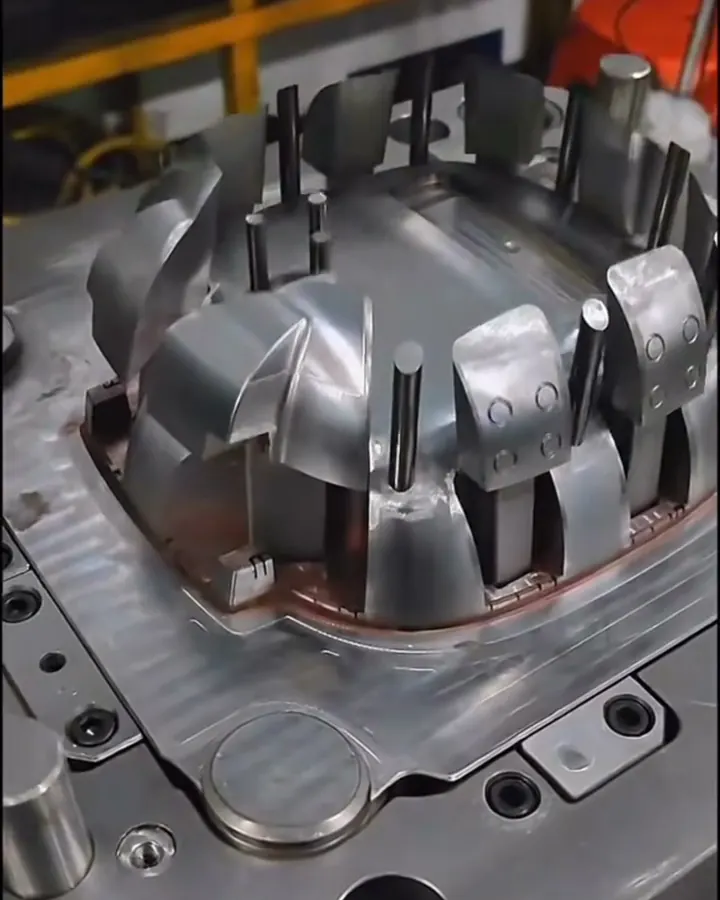
Fixes in the steel
Vents sized for the resin
A vent has to pass air and stop melt, and the line between the two depends on how runny the resin is. DuPont's dimensions for Delrin cavity vents: under 0.03 mm deep, more than 2 mm wide, a land no longer than 0.8 mm, then a channel about 0.3 mm deep to the outside. Runner vents can go deeper, 0.06 mm in its example, because flash on a runner does no harm. Stiffer resins tolerate deeper vents; the vent depth guide lists representative ranges by resin family, and how mold vents work explains the land-and-relief layout.
How many vents is a rule-of-thumb question. Fattori quotes two that experts use: vents about 1 in apart, or any number as long as at least 30% of the part perimeter is vented. He is candid that they work most of the time, not all of the time.
Vents also fill up and wear. DuPont says acetal molds with weak venting build up a white deposit where vents should be, and asks that vent depth be checked during maintenance and recut if it has dropped below 0.01 to 0.015 mm. Salhaney warns that the gases from a burn chemically etch the steel underneath, so a burn left running damages the cavity as well as the parts. Vent cleaning belongs in the routine for protecting your tooling.
When the parting line can't reach the trap
- Ejector pins. Salhaney describes three flats about 0.001 in deep ground on a pin, with the relief continued below. DuPont adds that pins which don't move with the ejector system clog and stop venting after a while.
- Porous inserts. Sintered steel such as Porcerax II, per Salhaney, is about 20 to 30% porous by volume with average pores of 7 or 20 microns; the 20-micron grade vents about 25% more than the same area of the 7-micron grade. They suit spots no parting line reaches, such as the bottom of a deep rib or pocket.
- Vacuum venting. John Bozzelli's line in Plastics Technology is that burns are a venting issue: vent the area, or if that cannot be done, pull a vacuum on the cavity. With the air drawn out during fill, there is little left to compress. It adds equipment to the tool and the press, so it is usually kept for parts that can't be vented any other way.
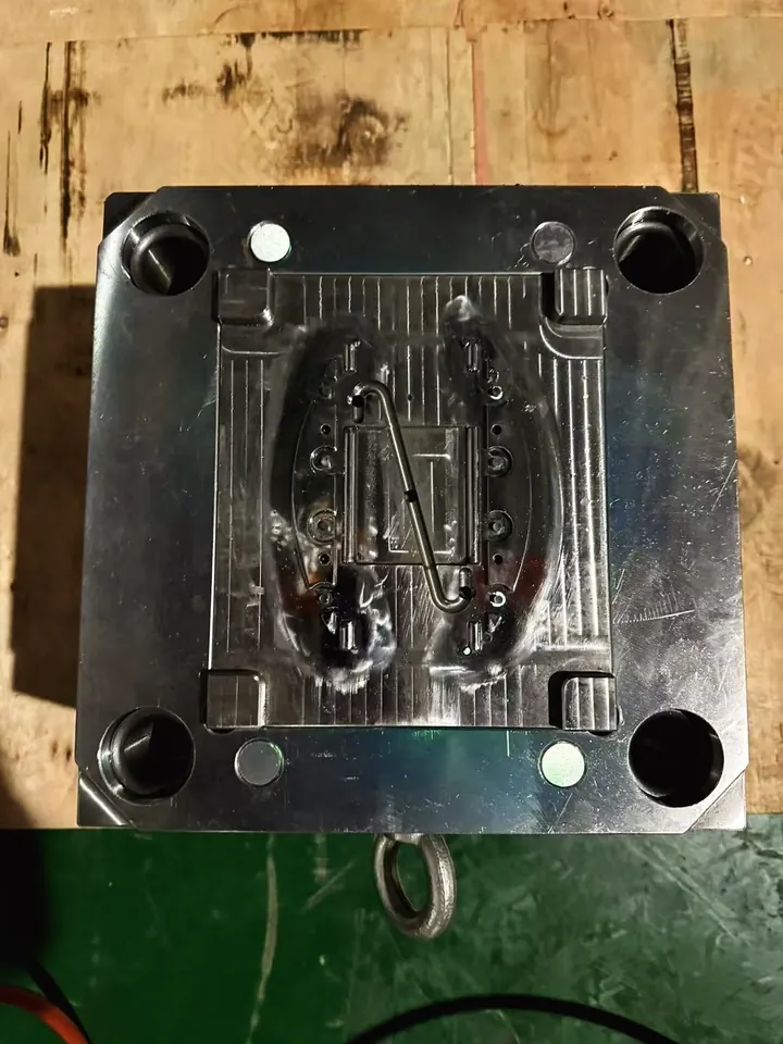
Moving or opening the gate
If the burn sits in a pocket no vent can reach and the part allows another gate position, moving the gate changes where the air ends up. Mold-Masters puts changing gate position or size at the end of its burn sequence, after vents and settings. It is the most involved fix, so do it once, backed by a fill study.
Fixes at the press
Profile only the end of fill
Slowing injection gives the air more time to leave, and it is the reflex fix. Fattori points out the cost: a slower fill raises the melt's viscosity, which can bring on short shots, so slowing the whole stroke trades one defect for another. Bozzelli says more than 80% of the processes he sets up use one fill velocity, and that flash or burns appearing only at certain speeds are mold issues rather than a reason to profile. Where a profile is justified, keep it narrow: hold the main fill speed and slow only the stretch where the front reaches the trap. His check is to make a short shot at each velocity change, weigh it, photograph it and note the fill time, so every step can be seen on the part.
Fattori also names the case where the slow stage becomes permanent: thin parts that must fill fast may not be ventable enough, and then injection velocity has to come down for the air to get out.
Fix the melt when the burn is degradation
Mold-Masters' burn sequence starts by clearing blocked vents, then lowers injection speed and pressure, then checks heaters, thermocouples, screw speed and melt temperature, before more venting and gate changes. Its dark-specks entry adds the melt-history causes: a barrel left idle for a long time, poor purging, and dead spots in gates, runners, the nozzle or the back flow valve. For melt burns, work through these:
- Measure the melt, not the setpoints. A failed heater or thermocouple can cook a zone while the display looks normal.
- Work out residence time. DuPont's equation: average hold-up time = resin weight in the cylinder x cycle time / shot weight. Its quicker version: maximum screw stroke x 2 x cycle time / actual screw stroke. The residence time calculator runs the barrel-capacity version.
- Look for hang-up in the hot half. DuPont points out that right next to the steel of the screw, check valve, adaptor, nozzle and hot runner the melt barely moves, so its residence time there is almost infinite; that is why color changes take so long. For Delrin it wants that steel kept below 190 °C, and it says shutoff nozzles cause hold-up that shows as brown streaks or gassing, especially once their moving parts wear. Mold-Masters' splay entry adds material trapped at the nozzle tip and friction burning in the gate, nozzle or hot runner; its burn entry lists friction burning too. Hot versus cold runners covers the trade-offs of the hot half.
- Check shear at the gate. A small gate heats the melt by friction at high speed; enlarging the gate is on Mold-Masters' burn list.
Worked example: an acetal latch housing
A hypothetical acetal housing measures 60 x 40 mm with a 2.0 mm wall, gated on one short edge, with a thin latch at the far end. Shot volume with runner is 25 cm³ on a 32 mm screw. DuPont's starting point for Delrin is about 1 s of fill per mm of wall thickness, so 2.0 s. At that speed the parts were clean but the latch sometimes ran short. Fill time was cut to 0.8 s to fill it, and now a whitish mark appears at the far corner beside the latch, which turns black under the hydrocarbon spray test.
How fast the air has to move. Screw area is π/4 x 32² = 804 mm², so the shot is 25,000 / 804 = 31.1 mm of stroke. At 0.8 s the melt flow is 25,000 / 0.8 = 31,250 mm³/s. The tool has four vents, each 3 mm wide and 0.025 mm deep, inside DuPont's limits: 0.075 mm² each, 0.30 mm² in total. With all four open the air would need 31,250 / 0.30 = about 104 m/s. Near the end only the vent nearest the latch is still open: 31,250 / 0.075 = about 417 m/s. These are the speeds the air would need, not what it manages; whatever can't get out in time is squeezed instead. At the original 2.0 s fill, 12,500 mm³/s, the last vent needed 167 m/s and the parts were clean. At 0.8 s it needs 2.5 times that, and the corner burns.
Against the rules of thumb. The perimeter is 2 x (60 + 40) = 200 mm. Fattori's 30% asks for 60 mm of vent width; four 3 mm vents give 12 mm, or 6%. Vents 1 in (25.4 mm) apart would mean about eight. The tool is under-vented by either rule.
The fixes, in order. As a test, keep 0.8 s pace for the first 90% of the stroke and run the last 10% at a quarter of that speed. The last vent then needs 7,813 / 0.075 = about 104 m/s, and fill time grows from 0.80 s to 0.72 + 0.32 = 1.04 s. If the mark clears, the diagnosis is confirmed, though the latch may start running short again, which is Fattori's warning. The cure goes in the steel: ten vents 6 mm wide and 0.025 mm deep cover the 30% (60 of 200 mm) with 0.15 mm² each. With three of them along the far end, three are still open as the front arrives: 31,250 / 0.45 = about 69 m/s at the full 0.8 s fill, well under the 167 m/s the old process ran clean at. Then try the process back at a single speed.
If the marks were brown streaks that moved around instead. Say the press has a 128 mm maximum stroke (4 screw diameters) and a 25 s cycle. DuPont's quick estimate gives 128 x 2 x 25 / 31.1 = 206 s, about 3.4 minutes. DuPont says standard Delrin at the recommended 215 °C melt tolerates a hold-up time of more than 30 minutes, and even its own long case, a 1-diameter stroke on a 1-minute cycle, works out to 8 minutes. Average barrel time is not the problem here, so the search moves to a local hang-up: the nozzle type and temperature, the hot runner tips, and any dead spot where melt sits far longer than the average.
| Cause | What you see | Fix |
|---|---|---|
| Trapped air / poor venting | A compact scorch at the last area to fill, in the same cavity and same place on every shot; the burned edge may also run slightly short. | Clean and re-cut the vents at that spot, and vent the runner and any flow junction so less air has to leave through the cavity. |
| Injection too fast at end of fill | The burn shows up only at higher fill speeds and gets worse as speed climbs, because the air is compressed faster than it can escape. | As a test, profile the stroke to slow only the last stage over the trap; keep corrected venting as the real cure so the part can run at one speed. |
| Melt too hot or high shear | Brown or black streaks that follow the flow and move around shot to shot, often worse after the press has stood idle, not pinned to one pocket. | Measure the actual melt temperature and bring it toward the resin's recommended range; open an undersized gate to cut shear heating. |
| Sharp gas-trap geometry | A scorch cornered in a blind pocket, a tall rib end, or the side opposite a side gate, where the parting line cannot reach to vent. | Relocate or resize the gate to sweep air toward the parting line, and add an overflow, pin flats, or a porous insert where no parting-line vent reaches. |
Diagnose in this order
- Read the part. A fixed spot at the last area to fill means trapped air; streaks or specks that wander mean melt. Check every cavity, because a burn in one cavity only points at that cavity's vents or gate; single vs multi-cavity tooling explains why cavities differ.
- Match it to a short shot. Stop a shot just before full. If the unfilled pocket is where the burn is, it is dieseling.
- Clean and measure the vents at that spot before changing settings. A clogged or worn vent is the simplest fix there is.
- Slow the last stage as a test, not as the cure.
- For melt burns, check heaters, thermocouples and actual melt temperature, then residence time, then the nozzle and hot runner for hang-up, purging between steps.
- Change the steel once: add vents, pin flats or a porous insert; vacuum if venting can't be added; move or open the gate last.
Tool fix or process fix?
A burn that appears in one fixed spot from the first trial shots is a tool problem, even when a slower last stage hides it. A burn that shows up on a tool that used to run clean usually means a vent has filled or worn, or something in the process changed, so the first question is what changed. Streaks from degraded melt are a process and machine question until the evidence points at a dead spot in the hot runner, which is tool work. A few cases shift the answer:
- Acetal: burns hide as faint whitish marks and vents collect white deposit, so use the spray test and schedule vent checks.
- Thin, fast-filling parts: venting alone may not keep up, so a slow last stage or vacuum stays in the process.
- Gas-heavy resins: polycarbonate and acetal give off far more volatiles than polystyrene and need more vent area for the same part; resin choice is covered in choosing the right resin.
Name burn marks in the defect list for first samples and agree the limit on parts at first-article review. The tool-or-process defects note places burns among the other common defects, and the defect troubleshooter suggests likely causes for a symptom that is harder to place.
Common questions
Are burn marks only cosmetic?
Not always. The scorched skin is degraded plastic, and DuPont notes that poor venting can also reduce properties at weld lines in acetal. The gases can etch the cavity steel, Salhaney writes in Plastics Technology, so a burn left running damages the tool as well as the parts. Treat a burn on a load-bearing or sealing feature as a functional defect.
Why did burn marks start on a mold that used to run clean?
Usually a vent has filled with deposit or worn shallow, or a setting changed, such as a faster fill. DuPont asks for acetal vents to be checked at maintenance and recut once they fall below 0.01 to 0.015 mm. If the vents measure right, look at actual melt temperature, heaters and the hot runner, because degraded melt can start burning with no change to the tool.
Can I just slow down injection to stop burn marks?
It often works as a test, because the air gets more time to leave. Fattori notes the catch: a slower fill makes the melt stiffer and can cause short shots. Bozzelli treats burns as a venting problem to be fixed in the mold. Slow only the last part of the stroke while the vents are corrected, then go back to one speed if the part allows.
What is the difference between burn marks and black specks?
A burn from trapped air sits at the last spot to fill and repeats every shot. Black specks are bits of degraded or contaminated material carried in with the melt, scattered and different on every part. Mold-Masters traces specks to dead spots in gates, runners, nozzles and the back flow valve, to barrels left idle and to poor purging, so the fix is in the melt path, not the vents.
Do hot runner molds get burn marks more often?
They add places where melt can hang up. DuPont says melt next to nozzle and hot runner steel barely moves and stays there almost indefinitely, and it limits that steel to 190 °C for Delrin. A hot runner with no dead spots, run at the right temperatures, need not burn, but brown streaks that survive every barrel adjustment should send someone to the manifold, nozzles and tips.
Sources
- Plastics Technology - Back to Basics on Mold Venting, Part 1 (Jim Fattori)
- Plastics Technology - Your Options for Mold Venting (Bob Salhaney, DME)
- Plastics Technology - Do You Need to Profile Injection Velocity? (John Bozzelli)
- DuPont - Delrin acetal resin molding guide (venting, hold-up time, troubleshooting)
- Mold-Masters - Hot Runner Troubleshooting Guide (burn marks, dark specks)
- NASA Glenn Research Center - Isentropic compression and expansion
Send the part file and the quantity you expect to run, and we'll review it before you commit to tooling. NDA first if you want one.
Send a part for reviewBook a 30-minute call